Page 14 / 23
There is the need to identify safety measures to protect the operator that are based on an estimation of
exposure in the actual conditions of use (taking account of all parts of the operating cycle such as the
times when the tool is switched off and when it is running idle in addition to the trigger time).
Examples of safety measures to protect the operator from vibration effects: maintain and service tool
and its accessories regularly, keep your hands warm, plan your work, take frequent pauses.
If any symptoms appear on hands or fingers, seek medical advice immediately.
11. Electrical Safety: Always check that the voltage of the power supply matches the voltage
indicated on the tool’s rating plate.
12. If the supply cord is damaged, it must be replaced by a special cord or assembly available from
the manufacturer or its service agent.
If the power cable or extension cord is damaged or cut during operation, immediately disconnect plug
from its main power source. Do not touch the cable or extension cord before unplugging from main
power.
13. Remarks:
The safety precautions and instructions given in this manual are unable to cover in detail all the
conditions and situations that may arise.
The operator and/or user must use common sense and caution when operating the product especially
for any matters that are not referred in the above
14. Warning
The use of any accessory or attachment, other than those recommended in this instruction
manual, may present a risk of injury to persons or animals and may cause damages.
The user and/or operator are responsible for any damages or injury caused to properties and/or
persons.
15. Have your tool repaired by a qualified person
Repairs should only be carried out by qualified persons using original spare parts, otherwise it may
result in considerable danger to the user.
IV. GETTING STARTED
Before any intervention on product, ensure that product is disconnected form its
power source.
4.1- Unpacking
Remove product from its packaging.
Check that tool and accessories are not damage
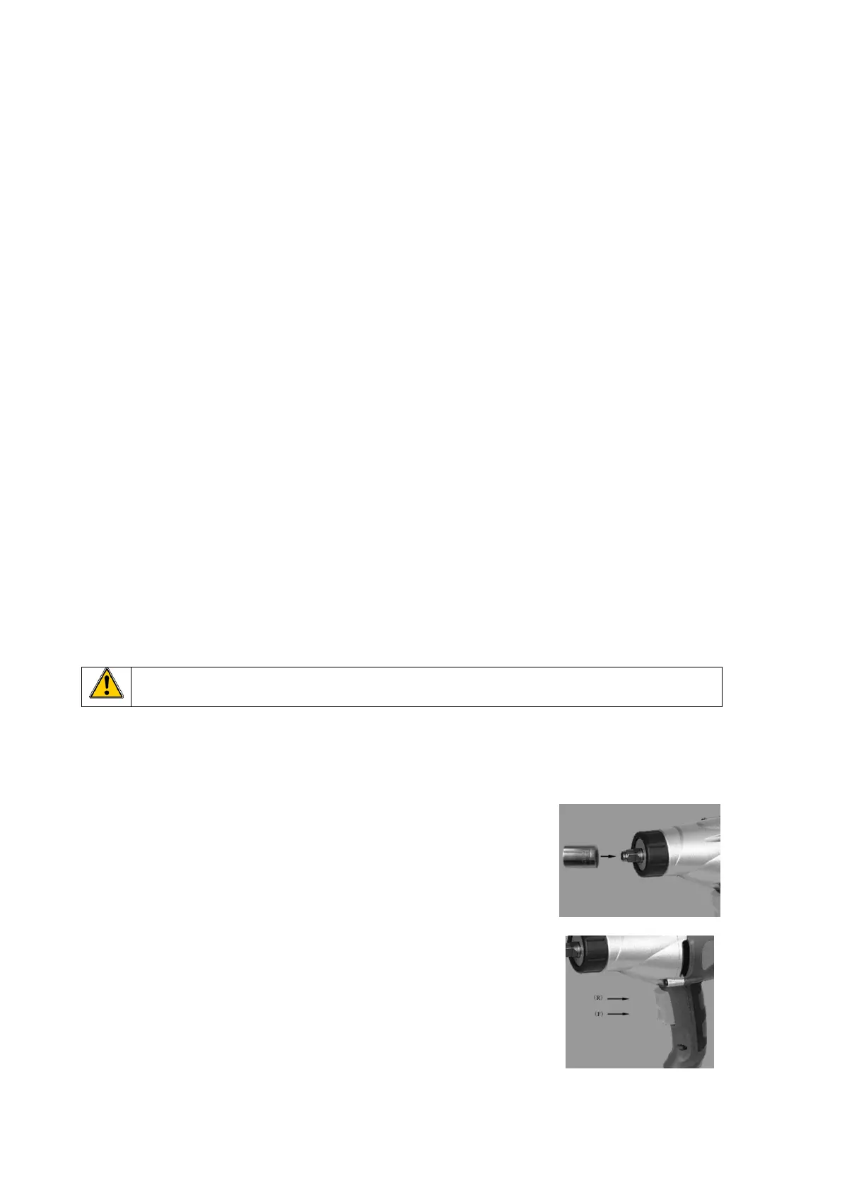
4.2- Inserting and removing a socket
- To install a socket on the anvil (Fig B):
Align the hole of the socket with the anvil and push down firmly.
Ensure it is centered and properly fixed.
- To remove a socket from the anvil :
Pull socket out firmly.
4.3- Switch (Fig. C)
To operate tool, press on switch (2) (Fig. A ).
To stop tool, release switch.
The switch has 2 positions :
- on top: (R) to reverse (go counter-clockwise)
- on bottom: (F) to go forward (clockwise)