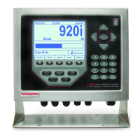
920i
®
Programmable HMI Indicator/Controller
Two-Card Expansion Board Installation
This document contains procedures for installing two card expansion boards in the deep universal, wall and panel mount
models of the 920i indicator. Procedures for each enclosure type are described in this document.
See the 920i manual (PN 67887) for general installation and configuration information, including option card slot numbering and
port assignments.
For applications using both six- and two-card expansion boards, connect the six-card board to the two card
board using cable ((PN 71799) for universal and panel mount units or cable (PN71780) for wall mount units.
The slot/location jumper on the two-card expansion board must be set to the 3–4 position for all standard
installations. The 9–10 position is used in special applications using both six- and two-card expansion boards.
For applications using both six- and two-card expansion boards, connect the six-card board to the two-card board
using either cable PN 71799 (panel mount units) or PN 71780 (wall mount units).
Figure 1. Two-Card Expansion Board
Part No. Description Qty
31596 Standoff, Male-FEM 4-40NC 5
69808 Board Assy, Expansion 2 1
71453 Standoff, PC Board 3
181032 Cable Assy, DC Power (180047 Only) 1
71758 Cable Assy, DC Power (71743 Only) 1
71779 Cable Assy, Ribbon 2.0'' 1
98807 Standoff, Male-Fem. 4-40 5
Table 1-1. Expansion Board Kit, PN 71743 and 180047
for Panel Mount or Deep Universal Enclosures
Part No. Description Qty
14822 Screw, Mach 4-40 NC x 1/4'' 4
15631 Cable Tie, 3'' Nylon 6
15650 Mount, Cable Tie 3/4'' 2
46192 Clamp, Flat Ribbon Cable 2
69808 Board Assy, Expansion 2 1
71452 Standoff, Male-FEM 4-40NC 12
179487 Cable Assy, DC Power, 4 Pin Connector (179488 only) 1
71757 Cable Assy, DC Power, 6 Pin Connector (69782 only) 1
71780 Cable Assy, Ribbon 23.5'' 1
Table 1-2. Expansion Board Kit, PN 69782 and 179488
for Wall Mount Enclosure
U3
J1
J2
J4
–6V
+6V
1
+3.3V
+5V
GND
+6V
–6V
1
J3
SLOT/LOCATION JUMPER
9–10
3–4
ISP
1
PN 71284 Rev BFebruary 05, 2018

 Loading...