Do you have a question about the RIEJU TANGO 125 and is the answer not in the manual?
Information on how manual updates are delivered and managed, including CD-Rom updates.
Explanation of warning symbols and their meanings used throughout the manual for safety and procedures.
Glossary of abbreviations and their definitions used in the workshop manual for clarity.
Essential guidelines and advice for safe and effective workshop practices to ensure safety and reduce risks.
Important advice for performing operations and handling components correctly, including cooling and tool usage.
Schedule and list of maintenance checks for the motorcycle at different service intervals (1,000, 3,000, 5,000 km).
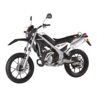
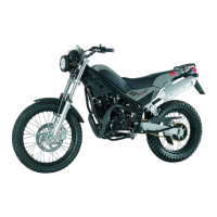
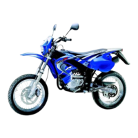
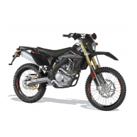
Detailed technical data, dimensions, weight, engine, and component specifications for the motorcycle.
Instructions for unpacking the motorcycle according to packaging indications and current regulations.
Visual inspection guidelines for plastic components and overall finish of the motorcycle for scratches or marks.
Information on locating engine and vehicle identification numbers for reference and ordering parts.
Details about the safety tag, its identification data, and importance for ordering spare parts.
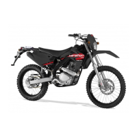
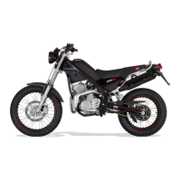
Diagrams and labels identifying key external components of the motorcycle from both left and right sides.
Identification and explanation of the motorcycle's controls, levers, switches, and dashboard elements.
Information on the motorcycle's numeric code keys and their functions for ignition, lights, and steering lock.
Instructions on how to activate and deactivate the motorcycle's steering lock mechanism using the key.
Guidance on checking the side stand for proper function, fixation, and hold-up system security.
Explanation of the various warning lights and indicators present on the motorcycle's dashboard.
Specifications for front and rear tyre dimensions and recommended pressure settings for optimal performance.
Procedure for checking and regulating tyre pressure at room temperature according to specifications.
Instructions for refueling the motorcycle, including capacity, safety precautions, and cleaning fuel residues.
Procedure for changing the transmission oil, including recommended oil type and capacity.
Guidelines for checking brake fluid levels and recommended brake fluid type (DOT 4) for safety.
Procedure for adjusting the engine idle speed using the gas adjustment screw for optimal engine response.
Instructions for adjusting and maintaining the correct tension of the transmission chain for optimal performance.
Step-by-step instructions for removing and reinstalling the motorcycle seat.
Procedure for removing the lateral cover, involving unscrewing a bolt from the back.
Instructions for removing the front lateral cover by unscrewing specific bolts located at the lower part.
Steps to remove the pillion seat, involving unscrewing two bolts and removing it from the front.
Procedure for loosening the clamp and unscrewing bolts to remove the muffler from the exhaust.
Detailed steps for removing the exhaust system, including loosening clamps, bolts, and pulling the muffler.
Instructions for disconnecting the positive and negative cables and removing the motorcycle's battery.
Procedure for removing the rear direction indicators, involving cutting a clamp and loosening a screw.
Steps to disconnect the taillight terminal, loosen screws, and pull the cable to remove the light assembly.
Instructions for removing the air filter cover and the filter element after removing the seat and lateral cover.
Procedure for disconnecting the regulator from the wiring and unscrewing a bolt for its removal.
Steps to disconnect the intermittence station from the general wiring and extract it from its rubber housing.
Instructions for disconnecting the CDI unit from the wiring and extracting it from its rubber housing.
Steps to remove the filter box, involving unscrewing bolts, loosening tubes, and lifting the rear chassis.
Procedure for removing the shock absorber by unscrewing bolts that hold it to the chassis and frame.
Instructions for removing the gear lever by unscrewing the fixing bolt and pulling it carefully.
Steps for removing the fuel tank, including turning off the tap, unscrewing bolts, and separating the cover.
Procedure for removing the carburettor, involving loosening clamps, unscrewing the top cover, and disconnecting cables.
Instructions for removing the side stand by removing the tensioning spring and unscrewing the fixing bolt.
Steps for removing the front mudguards by unscrewing four bolts that hold them to the fork.
Detailed procedure for removing the engine, including disconnecting cables, terminals, and unscrewing mounting bolts.
Instructions for disconnecting the front direction indicators from the wiring and unscrewing the mounting bolt.
Procedure for removing the headlight by disconnecting the wiring terminal and unscrewing mounting bolts.
Steps for removing the dashboard, involving disconnecting odometer connections and unscrewing top bolts.
Procedure for removing the front brake pump, including disconnecting micro-switch terminals and unscrewing bolts.
Steps for removing the clutch lever by disconnecting transmission and unscrewing two mounting bolts.
Procedure for removing the handlebar by unscrewing four mounting bolts and loosening lateral screws.
Instructions for removing the front brake pin by unscrewing the join and mounting bolts.
Procedure for removing the rear brake pin by unscrewing the join and mounting bolts.
Steps for removing the front wheel by loosening the fixing bolt and unscrewing the axle located at the fork.
Instructions for removing the odometer sensor by disconnecting wiring and unscrewing its mounting screw.
Procedure for removing the front brake disc by unscrewing the bolts that hold the disc to the wheel hub.
Steps for removing steering components, including handlebar bolts, lateral screws, top nut, and axle nut.
Instructions for removing the front footrest by unscrewing the bolt that holds it to the lower nut.
Procedure for removing the rear footrest by unscrewing the bolt that holds it to the lower nut.
Steps to remove the rear brake lever by unscrewing the fixing bolt.
Procedure for removing the drive chain guard by unscrewing two mounting bolts.
Instructions for removing the transmission chain, including the securing clip of the link.
Steps for removing the rear brake pump, involving disconnecting stop switch cable and removing a clamp.
Procedure for removing the kick-starter lever by unscrewing the nut and pulling the lever.
Instructions for removing the swing arm by unscrewing a nut and removing the axle.
Torque table specifying tightening values (N*m and Kg*m) for various motorcycle elements.
| Engine Type | Single-cylinder, 4-stroke |
|---|---|
| Cooling System | Air-cooled |
| Fuel System | Carburetor |
| Transmission | 5-speed manual |
| Front Suspension | Telescopic fork |
| Front Brake | Disc |
| Rear Brake | Disc |
| Maximum Torque | 9.5 Nm |
| Rear Suspension | Mono shock absorber |