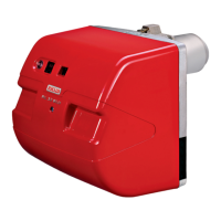
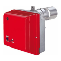
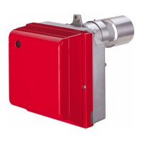
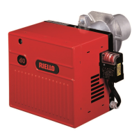
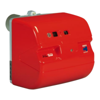
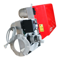
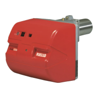
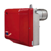
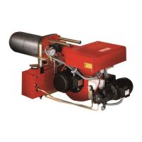
The Riello 40 Series BF3 and BF5 are residential oil burners designed for use with boilers or furnaces. These burners are engineered to provide efficient and reliable heating, with a focus on ease of installation and maintenance. The manual emphasizes that while initial settings are provided, proper combustion test equipment is crucial for verifying optimal performance in any given installation.
Function Description
The Riello BF3 and BF5 burners are designed to atomize and ignite fuel oil, creating a stable flame for heating applications. They operate by drawing in combustion air, mixing it with atomized fuel, and then igniting the mixture within the combustion chamber of the heating unit. The primary control system manages the ignition sequence, flame sensing, and safety lockout functions, ensuring safe and consistent operation. The pump delivers fuel at a regulated pressure to the nozzle, which then sprays the oil into the combustion head. An ignition transformer provides the high voltage necessary to create a spark for ignition. Airflow is controlled by an adjustable air damper and turbulator, allowing for precise tuning of the combustion process to achieve optimal efficiency and low emissions. The burner can be configured for either single-line (gravity feed) or two-line (lift system) oil supply, depending on the installation requirements and fuel tank location.
Usage Features
The Riello BF3 and BF5 burners are designed for straightforward installation and setup, although the manual stresses the importance of professional verification of combustion results.
- Mounting: The burner offers two primary mounting methods: a universal flange for direct attachment to the boiler or furnace, and an optional pedestal mount for situations where direct attachment is not feasible. The universal mounting flange allows for precise positioning of the air tube within the combustion chamber, with specific recommendations for wet-based and dry-based chamber applications. For dry-based appliances, the use of an amulet or cera-felt sleeve on the end cone is suggested to prevent burn-off and improve sealing.
- Electrical Connections: The burner can be integrated into either a direct line voltage (120V AC 60 cycle) or low voltage (24V AC 60 cycle) control circuit, using Riello or Honeywell R8038A 24V relays. The control box is designed to be easily removable for completing electrical connections to the sub-base. A remote sensing feature for safety lockout is available, providing a 120Vac power source at a specific terminal on the sub-base when a lockout occurs, allowing for remote monitoring.
- Nozzle Placement: Selecting the correct nozzle and pump pressure is critical for achieving the desired firing rate. The manual provides setup charts to guide the installer in choosing the appropriate nozzle and initial pump pressure settings. The nozzle adapter is easily accessible for insertion and secure tightening of the nozzle.
- Drawer Assembly: The burner features a drawer assembly that can be easily removed for maintenance tasks such as nozzle replacement or electrode adjustment. This involves loosening a screw, unplugging the control box, and removing the air tube cover plate.
- Turbulator Adjustment: The turbulator, which helps mix air and fuel for efficient combustion, can be adjusted to fine-tune the flame. A screw and retaining nut mechanism allows for alignment with specific index numbers provided in the burner setup charts.
- Oil Line Connections: The pump is shipped configured for a one-line system but can be converted to a two-line system by installing a by-pass plug. Detailed instructions are provided for installing the by-pass plug and connecting the suction and return lines. The manual includes tables for determining appropriate pipe lengths for both single-line (gravity feed) and two-line (lift system) configurations, considering factors like height and pipe diameter. It also highlights the importance of using British Parallel thread design for pump port connections and warns against using NPT threads directly.
- Pump Purge: Before initial operation, the pump and oil lines must be purged of air. For single-line systems, this involves attaching a hose to the bleeder plug, loosening it, and allowing oil to flow until clear. For two-line systems, two options are provided: either using a light source to activate the photocell and run the burner in prepurge mode, or using a jumper wire to operate the motor and pump without the control module until oil flows clear from the bleeder port.
- Air Damper Adjustment: The air damper controls the amount of combustion air entering the burner. Initial settings are made by aligning the top edge of the air damper with a number specified in the setup chart. Further adjustments can be made with the burner cover in place by turning a screw, with indicators for increasing (+) or decreasing (-) combustion air. The final position of the air damper should be set using combustion instruments to achieve maximum CO2 and a smoke reading of zero.
- Intake Air Layout: The manual provides a typical layout for BF burner intake air in chimney applications, emphasizing the use of an approved air intake kit and minimizing intake air run length. It also suggests insulating intake air venting to prevent condensation and corrosion and using a vacuum breaker balancer to ensure sufficient air supply even if the main source is blocked.
Maintenance Features
The design of the Riello BF3 and BF5 burners incorporates features that facilitate routine maintenance and troubleshooting.
- Easy Access to Components: The burner cover, control box, and air tube cover are designed for easy removal, providing access to internal components such as the drawer assembly, nozzle, electrodes, and turbulator for inspection, cleaning, or replacement.
- Drawer Assembly Removal: The ability to slide out the complete drawer assembly simplifies tasks like nozzle replacement and electrode adjustment, as these components are housed within this assembly.
- Electrode Setting: The manual provides precise dimensions for electrode setting, which is crucial for reliable ignition. These dimensions must be observed and verified during maintenance.
- Oil Filter: An external oil filter is required in the fuel line between the tank and the burner pump, even though the pump has an internal strainer. This filter should be replaced at least once a year, and its container thoroughly cleaned, to prevent contaminants from reaching the pump and nozzle.
- Troubleshooting Chart: A comprehensive troubleshooting chart is included in the manual, outlining common issues and their potential causes, along with recommended solutions. This chart covers scenarios such as the burner not starting, staying in pre-purge, immediate flame dropout, or locking out after trial for ignition, and provides guidance on checking electrical connections, pump function, coil circuits, and other components.
- Spare Parts List: A detailed spare parts list, complete with codes and descriptions, is provided to assist in identifying and ordering replacement components for both BF3 and BF5 models. This ensures that the correct parts can be easily sourced for repairs.
- Precautionary Guidelines: The manual includes a section on precautions, covering aspects like ensuring adequate air for combustion, checking chimney sufficiency, and proper electrical connections. These guidelines are essential for safe and long-term operation of the burner.
- Control Burner Operation: Installers are instructed to check out the burner and explain its operation to the homeowner, leaving the Owner's Instruction sheet for future reference. This promotes proper user understanding and maintenance.