SAFE Z.2
121110
4
Mechanische
Montage
mechanical
mounting
Montage und Inbetriebnahme
Für eine sichere Funktion muß die Zwei-
handschaltung in ein staub- und feuchtig-
keitsgeschütztes Gehäuse eingebaut wer-
den (IP54).
Montieren Sie das Zweihandbe-
dienungsgerät auf eine Norm-
schiene.
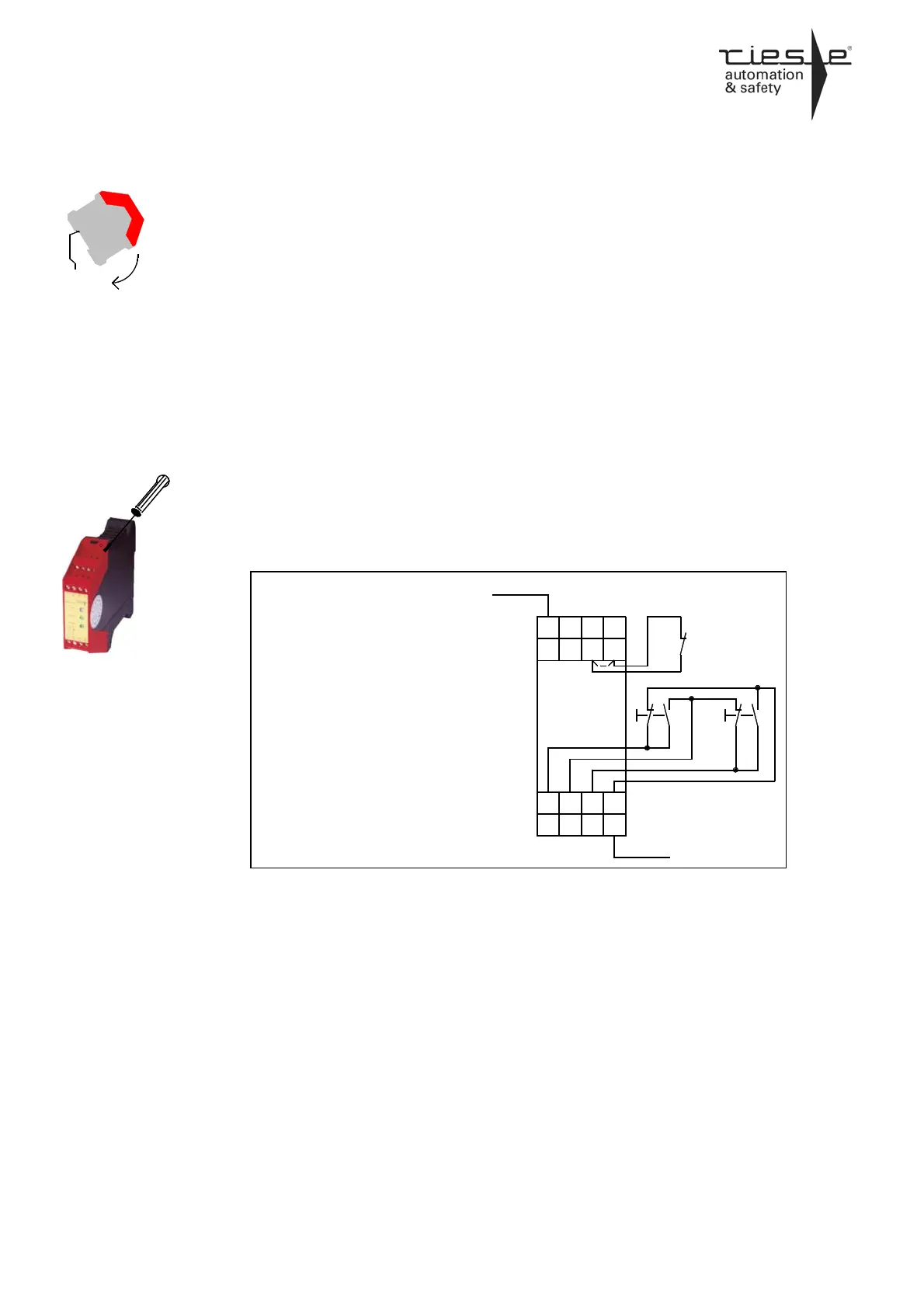
Elektrischer Anschluß
Führen Sie die Verdrahtung entsprechend
des Anschlußplanes durch.
1. Anschlußplan für das Zwei-Hand-
Bedienungsrelais SAFE Z.2 entspre-
chend der Berufsgenossenschaft,
Fachausschuß Eisen und Metall III ZH
1 / 456 (02.78) und DIN EN 574
(02.97) für Type I - III c
* - Rückführung oder Brücke
* - contol loop or bridge
2. Anschluss der Versorgungsspannung
Versorgungsspannung DC Version:
Schließen Sie die Versorgungsspan-
nung +24V an die Klemme A1 und
GND an die Klemme A2 an.
Versorgungsspannung AC Version:
Schließen Sie die Versorgungsspan-
nung an die Klemmen A1 und A2 an.
Schließen Sie den Schutzleiter an die
Klemme PE an. Die Verbindung muss
lösbar sein. Bei der Gerätevariante
24V AC/DC darf der Schutzleiter nicht
angeschlossen werden.
Mounting and opening
The unit should be panel mounted in an
enclosure rated at IP54 or better, other-
wise dampness or dust could lead to func-
tion impairment.
There is a notch on the rear of the
unit for DIN-Rail attachment.
Electronic connection
Carry out the wire appropriate the connec-
tion plane.
1. Connection plane according to the
two-hand-control-relay SAFE Z.2 from
cooperative line, committee line of iron
and metal III ZH 1 / 456 (02.78) and
DIN 574 (02.97) for type I - III c.
2. Wiring of the supply voltage
Supply voltage DC version:
Connect the supply voltage +24V to
terminal A1 and GND to terminal A2.
Supply voltage AC version:
Connect the supply voltage to termi-
nals A1 and A2.
Connect the protective conductor to
the terminal PE. The connection has
to be unlockable. With type 24V
AC/DC it is not allowed to connected
the protective conductor to PE.
32
S21
14 24
S11 S12
A2
M (N)
S22
23
Y1
A1 13
L+ (L)
34
S2S1
31
Y2
*