Programmable Relay ● User Manual for ELC, EXM and PR Series 163 2020 v6.0 ● © Rievtech Co.,
Ltd. ● www.rievtech.com
The shift register function can be used to read an input
value and to shift the bits. The output value corresponds
to the configured shift register bit. The shift direction can
be changed at a special input.
The function when started reads this
input value.
The SFB is started with a positive
edge (0 t 1 transition) at input Trg
(Trigger). A 1 to 0 transition is
irrelevant.
You define the shift direction of the
shift register bits S1...S8 at the Dir
input:
Dir = 0: shift up (S1 >> S8)
Dir = 1: shift down (S8 >> S1)
Shift register bit that determines
the value of output Q.
Possible settings: S1 ... S8
Retentivity set (on) = the status is
retentive in memory.
The output value corresponds to
the configured shift register bit.
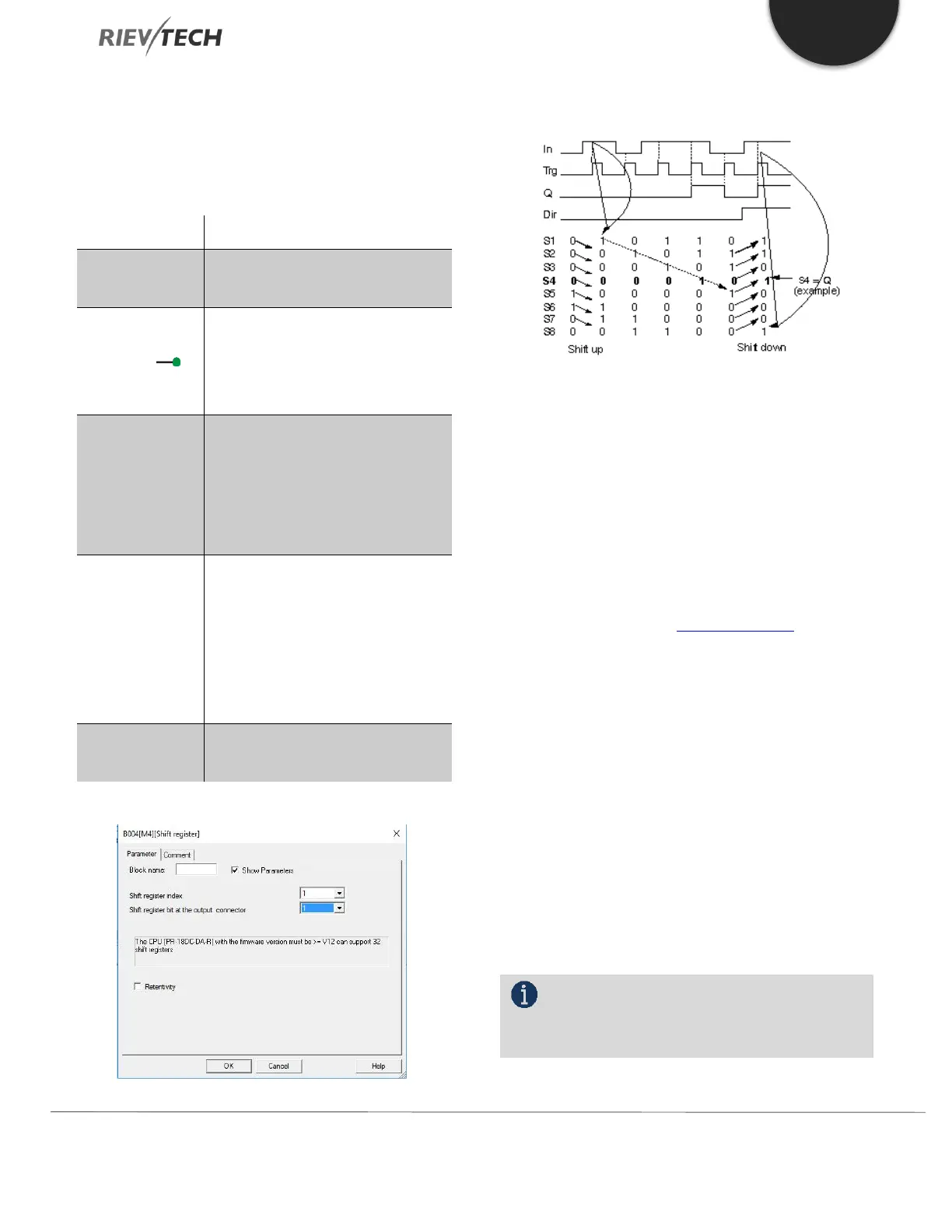
Timing diagram
Setting the Par parameter
This special function is not available in parameter
assignment mode.
Description of function
The function reads the value of input In with a positive
edge (0 to 1 transition) at input Trg (Trigger).
This value is written to shift register bits S1 or S8,
depending on the set shift direction:
Shift up: S1 accepts the value of input In; the
previous value of S1 is shifted to S2, S2 is shifted to
S3, etc.
Shift down: S8 accepts the value of input In; the
previous value of S8 is shifted to S7, S7 is shifted to
S6, etc.
Q outputs the value of the configured shift register bits.
If retentivity is not enabled, the shift function restarts at
S1 or S8 after a power failure.
NOTICE:
The special function shift register can be used
only once in the circuit program.
 Loading...


