Retentive on-delay (Ta) Wiping relay(pulse output)
(Ta)
Edge triggered wiping relay (Ta)
Asynchronous pulse generator (Ta)
Stairway light switch (Ta) Multiple function switch
(Ta)
Stopwatch (Ta)
Parameter p (number of decimals)
Parameter p applies only to the display of the Ax value in
a message text.
Description of the function
The function reads the value of the signal at the analogue
input Ax.
This value is multiplied by the value of parameter A (gain).
Parameter B (offset) is added to the product, as follows:
(Ax * Gain) + Offset = Actual value Ax
The function block calculates the proportion of the value
Ax to the range. The block sets the digital output Q high
for the same proportion of the PT (periodic time)
parameter and sets Q low for the remainder of the time
period.
Examples of Timing Diagrams
The following examples show how the PWM instruction
modulates a digital output signal from the analogue input
value:
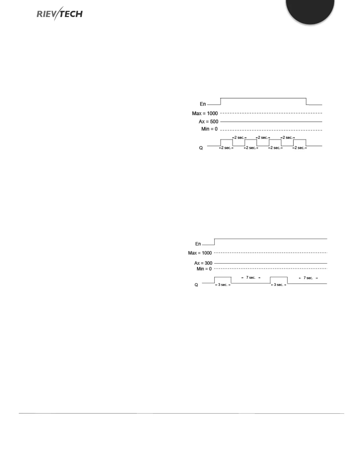
Example 1
Analog input value: 500 (range 0...1000)
Periodic time T: 4 seconds
The digital output of the PWM function is 2 seconds high,
2 seconds low, 2 seconds high, 2 seconds low and
continues in that pattern as long as parameter "En" = high.
Example 2
Analog input value: 300 (range 0...1000)
Periodic time T: 10 seconds
The digital output of the PWM function is 3 seconds high,
7 seconds low, 3 seconds high, 7 seconds low and
continues in that pattern as long as parameter "En" = high.
Calculation rule
Q = 1, for (Ax – Min) / (Max – Min) of time period PT
Q = 0, for PT – [(Ax – Min) / (Max – Min)] of time period
PT.
Note: Ax in this calculation refers to the actual value Ax as
calculated using the Gain and Offset. Min and Max refer
to the minimum and maximum values specified for the
range
 Loading...


