Special feature.
The standard output frequency of xLogic is up to 30Hz. By
configuring the PWM function block as shown below a
frequency of up to 10 kHz can be obtained on the
following CPU outputs:
PR-12 – Outputs Q3 and Q4
PR-18 and ELC-22 (PNP Transistor) – Outputs Q5 and Q6
PR-24 and PR-26 – Outputs Q7 and Q8
By the following configuration:
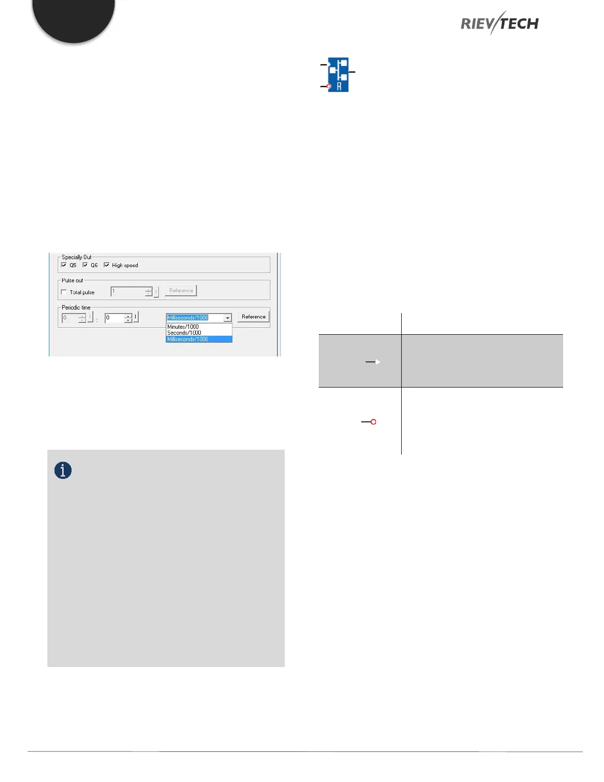
If the special output is selected in the property dialogue
box of PWM block, then the unit of “periodic time” will be
changed from s:1/100s to s:1/1000s, so if you input 3
(1/1000s), then its frequency will be 1000/3 Hz.
NOTICE:
1. The periodic time must be no less than 3 ms.
2. If the specific output is selected in the
property dialogue box of PWM block, then the output
pin of the PWM function block cannot be linked as an
input to other blocks.
3. Q3, Q4 in the above dialogue box correspond
to Q3, Q4 of a PR-12 CPU or Q5, Q6 of a PR-18 and
ELC-22 CPUs or Q7 and Q8 of the PR-24 and PR-26
CPUs.
4. The output frequencies of the special channels
of the CPUs can be different ONLY if ONE box is ticked.
If BOTH boxes are ticked, the outputs will have the same
maximum frequency.
Modbus Read
Description of function
When there is a high level at En, the Modbus Read block
will be activated and the xLogic shall communicate with a
peripheral device as a master via RS232 or RS485 interface.
Furthermore, the output will be switched on when
communication is established successfully. Otherwise,
the output (Q pin) remains “off” which means
communication has failed.
A signal at input R resets output Q and disables this block
at the same time
 Loading...


