Slave address: 1 is a default.
Communication protocol: Modbus
(RTU)
Communication parameter: baud
rate (BPS), Data bits, Stop bits,
Parity, Overtime (response timeout)
Comm Type: RS232 or
RS485(Communication interface of
xLogic)
Data register Index: High Low /Low
High
Command:
01 Read coils(0x)
02 Read Discrete Input(1x)
03 Read Holding Registers(4x)
04 Read Input Registers(3x)
Register start address, count
Q is set or reset depending on the
communication status.
Successful communication, Q=1;
Failed communication, Q=0;
NOTICE:
Data register Index: High Low /Low High
For example, when the HighLow index is set, and the
data 0x0012 was read and saved to AQ, then AQ=
0X0012; however, when the LowHigh index is set, then
AQ= 0x1200.
Refer to the Modbus RTU Communication Manual for
more information.
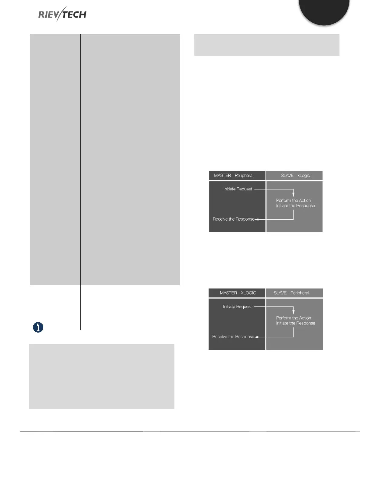
Description of the function:
In the configuration of our xLogic communication, the
xLogic usually serves as a slave via Modbus RTU Protocol
and can communicate with a master directly. That’s to say,
any device communicating with xLogic sends a command
to it, and then its response will be sent out only when the
xLogic has received the command, just as the below figure
shows:
However, the “Modbus Read” or “Modbus Write” (see next
chapter) function blocks should be used if xLogic shall be
required to play a role of master to communicate with
other slave devices. As the following figure shows:
When you put the “Modbus read” or “Modbus Write”
function block in your program the xLogic CPU will behave
as a Modbus RTU Master.
 Loading...


