Programmable Relay ● User Manual for ELC, EXM and PR Series 170 2020 v6.0 ● © Rievtech Co.,
Ltd. ● www.rievtech.com
The number setting of Q, I, AQ are continuous. AQ12
cannot be set as AQ 12 and should be set AQ 4 as above
figure shows.
The following table shows how to set the addresses.
NOTICE:
This table also can be applied to the
configuration of the Modbus Write function block.
Expansion1
(Address is 1)
The data format of instruction:
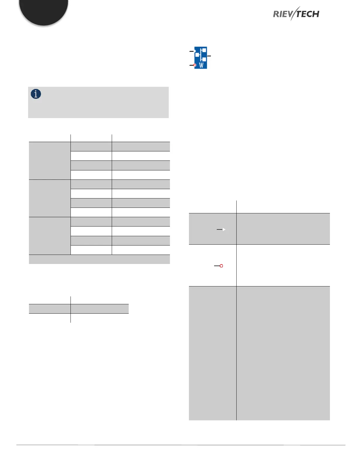
Modbus Write
Description of function
With a high level at En, the Modbus Write block will be
activated and the xLogic could communicate with
peripheral as a master via RS232 or RS485 interface and
the output of the block will be switched on when the
communication is established successfully. Otherwise, the
output (Q pin) is kept “off” which means communication
has failed.
A signal at input R resets output Q and disables this block
at the same time.
A high signal at En input will enable
“Modbus Write” function block to be
activated
Reset the value read from peripheral
and set the output to 0 via the R
(Reset) input.
Reset has priority over En
Slave address: 1 is a default.
Communication protocol: Modbus
(RTU)
Communication parameter: baud
rate (BPS), Data bits, Stop bits,
Parity, Overtime (response timeout)
Comm Type: RS232 or RS485
(Communication interface of xLogic)
Data register Index: High Low
/Low High
 Loading...


