Programmable Relay ● User Manual for ELC, EXM and PR Series 171 2020 v6.0 ● © Rievtech Co.,
Ltd. ● www.rievtech.com
Command:
05 Write Single Coil
06 Write Single Register
15 Write Multiple Coils
16 Write Multiple Registers
Register start address, count
Q is set or reset depending on the
communication status.
Successful communication, Q=1;
Failed communication, Q=0;
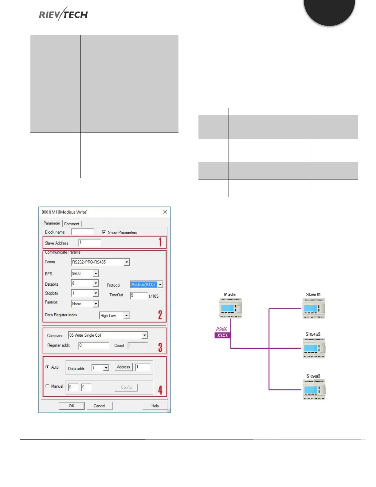
The configuration of a “Modbus Write” block is shown
below:
1. Slave Address: 1 is a default
2. Communication parameters: BPS is baud rate, Stop
bits, Data bits
Communication type: RS232 or RS485 interfaces of
xLogic CPU.
3. Command, register address, and register count
Force the switch status of single
coil (00000-0XXXX)
Force Single Coil
(output)
Pre-set the data of a single
register (40000-4XXXX)
Set single output
register
Force multi-coils on/off bit
(00000-0XXXX)
Write multi-holding registers
data (40000-4XXXX)
4. Data that is to be written to the Slave can be configured
in one of two ways. One is in auto mode, this
data uses the flags in the program, such as F, M, AF, AM,
I, Q and AQ. The second, manual mode is used to set a
fixed value or bit status.
Example 1