Write the I2 bit status of Master xLogic to Slave No1
xLogic and control Q1 of the slave via RS485 port. The
program of a master would be as follows:
I1 of the master is used to control the communication. If
I1 is high and the communication is established
successfully, one alarm message (text message block) will
be displayed on the LCD. Then Q1 of slave No.1 will be
controlled by I2 of the master. If I2 is high, Q1 of slave
No.1 would be ON and if I2 is low, Q1 of the slave would
be OFF.
NOTICE:
The Q1 of the Slave must be free – No other
blocks can be connected to its input pin.
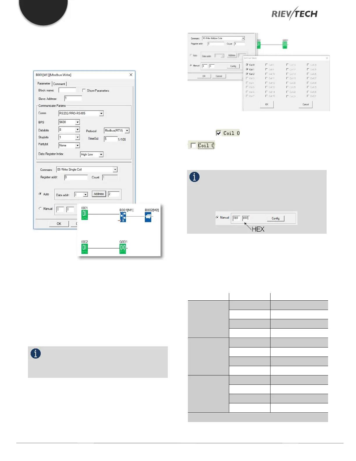
Example 2, manual mode input value
The above configuration is to force Q1, Q2, Q3 of Slave
No.1 ON. "means pre-set the BIT 1 and
"means pre-set the BIT 0 ”Coil 0” is
corresponding to the start address, Here it is Q1.
NOTICE:
The manual input value is Hex data .it contains 4
bytes. If you want to write a decimal value to the register
of the slave, it must be converted to Hex format first.
4. The following table shows how to set each output.
Note: This table also applies to the Modbus Read function
block
 Loading...


