Programmable Relay ● User Manual for ELC, EXM and PR Series 175 2020 v6.0 ● © Rievtech Co.,
Ltd. ● www.rievtech.com
AQ – Analogue
outputs
RTC – Real Time Clock
VW – Word blocks
o For Modbus Command 04,
options are:
AF- Analogue flags
AQ – Analogue
outputs
VW – Word blocks
o For Modbus Command 15,
options are:
Q – Physical outputs
F – Digital Flags
I – Physical inputs
o For Modbus Command 16,
options are:
AF- Analogue flags
AQ – Analogue
outputs
RTC – Real Time Clock
VW – Word blocks
AI – Analogue inputs
Manual: Use coils max.32 (FFFF
FFFF)
Identification String: Max. 20-
characters
Data: Start Address and
Count (No. of registers) for
Types:
o Digital Inputs, Digital
Outputs, Analogue Inputs,
Analogue Outputs, Digital
Flags, Analogue Flags, M
Registers and AM Registers
When communications established
with Slave (Server), the output is set
High
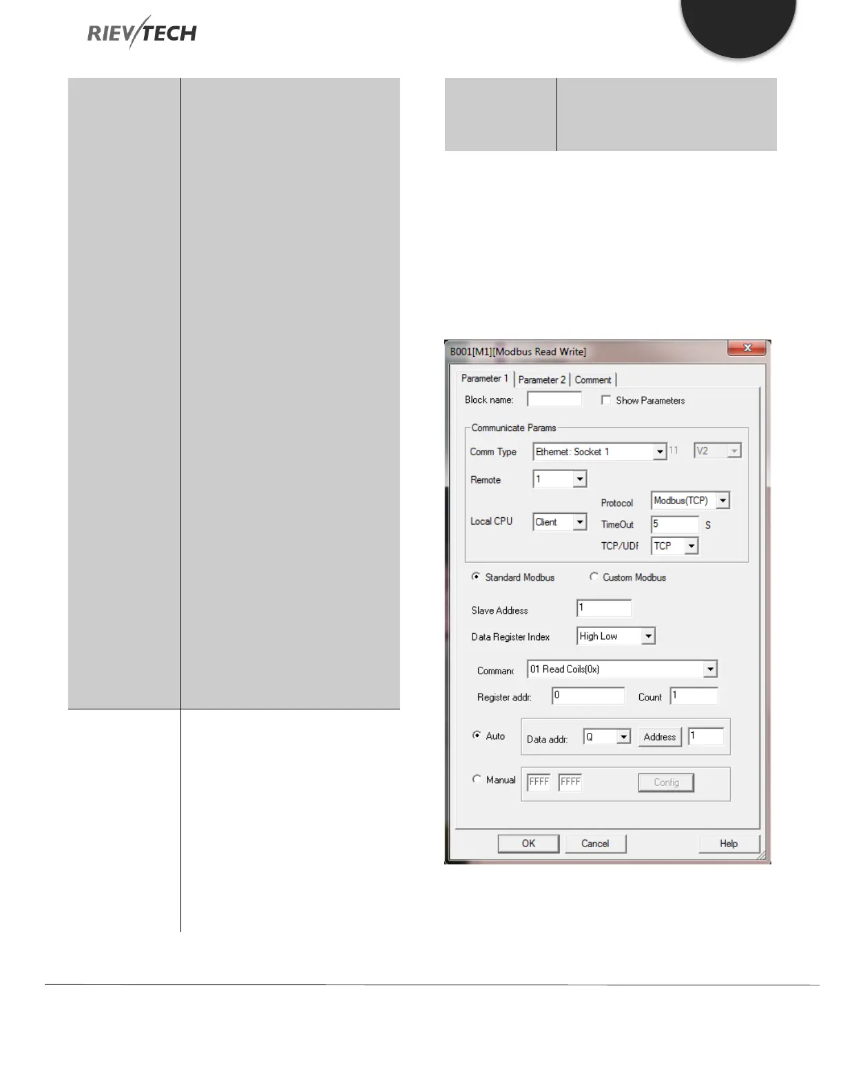
Example 1 Local CPU as Master (Client)
The CPU is to work as a Master (Client) using standard
Modbus/TCP to read one coil (Count) from the Slave
(Server) at address register 0 and write the value to the
CPUs first output coil, Q1.
Remote 1 is the channel that belongs to the Slave and its
IP address (192.168.0.227) and port number (5001) is
configured using Tools Transfer Web Server Config: