Programmable Relay ● User Manual for ELC, EXM and PR Series 178 2020 v6.0 ● © Rievtech Co.,
Ltd. ● www.rievtech.com
07 : type code (07 means the M status)
01 : length field = number of bytes of M(Function block
status(1/0))
04: status of the M (M1=0,M2=10,M3=1,M4=0)
0d 08 00 00 00 00 00 00 01 c2
0d : type code (0d means the AM value)
08 : length field = number of bytes of AM
00 00 00 00 00 00 01 c2: AM value (AM1=00 00,AM2=00
00,AM3=00 00,AM4=01 c2)
Response expected from Server (Slave)
00 00 00 00 00 02 01 8b
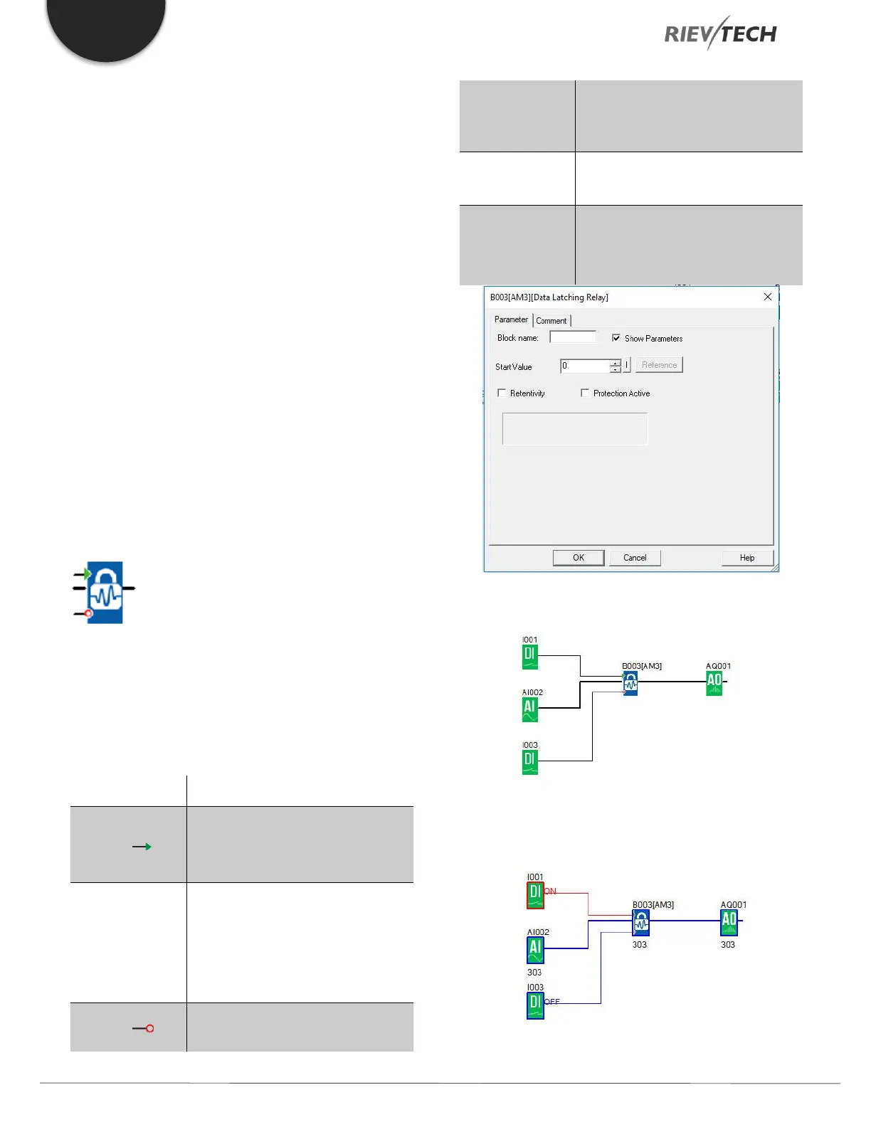
Data Latching Relay
Description of function
This special function saves the process variable of an
analogue input to memory and returns it at the analogue
output.
Save the Ax to memory and return
it at the analogue output with a
signal at input S (Set).
Input the analogue signal to be
amplified at input Ax. Use the
analogue inputs, the block number
of a function with analogue output,
or the analogue outputs.
Reset analogue output AQ to 0
with a signal at input R (Reset).
analogue Output AQ is reset if S
and R are both set (reset has
priority over set).
Value range for Start value: -
32768...+32767
Analog output
Value range for AQ: -
32768...+32767
Example
When I1 is HIGH, the value of AI2 will be saved to memory
and sent to AQ1 as follows:
 Loading...


