When I3 is HIGH, the value of this function block will be
reset to 0.
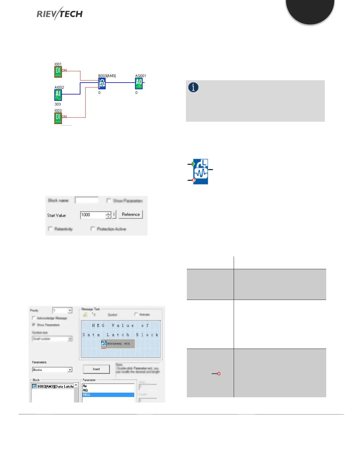
1. Start value – You can set a start value for the data latch
relay block, which can be a fixed value or use the value
from an existing programmed block by using the
‘Reference’ button.
2. The HEG value of the data latch relay can be modified
at runtime by pressing the OK key for 3 seconds on the
CPU front LCD.
The HEG value of data latch relay block also can be
displayed with a decimal point if required.
There is a Modbus address for the HEG, so you can also
change the HEG value by a Modbus Master (Touchscreen
etc.). You can find the address in the Modbus RTU User
Manual or written in next to the block in your program.
NOTICE:
If your firmware CPU doesn’t support this
function, you can download the firmware update
package from our website.
Long Data Latching Relay
Description of function
This block can be used to store an analogue value to
memory. When the Set pin ‘S’ is set High, the analogue
value referenced by the block will be stored. When the
Reset pin ‘R’ is set High, the value will be reset to 0.
Only when there is a low to high
trigger at Set pin, the block will store
the referenced value to memory.
The block referenced which contains
the analogue value to be stored. This
can be any pre-defined analogue
type block such as inputs, flags,
timers, maths, etc.
A trigger of Low to High on the
Reset (Input R) pin will set the
memory to 0. Reset has priority
over Input S. If both pins are High
Pin R has priority over Pin S.
 Loading...


