This is the multiplexer output.
This value depends upon the state
of the SELECTION input.
If the SELECTION input is:
inactive: the OUTPUT corresponds
to CHANNEL A,
active: the OUTPUT corresponds
to CHANNEL B.
NOTICE:
1. If the SELECTION input is not connected, then
it is considered to be inactive.
2. If CHANNELS A or B are not connected, then
they are set to 0.
Multiplexer
Description of function
This function multiplexes the WORD inputs. It is used to
route the value of one of the inputs selected by the
ADDRESS input to the output. The input is routed to the
output on each rising edge of the VALIDATION input.
The BASE ADDRESS parameter allows several blocks to be
used at the same time to multiple inputs.
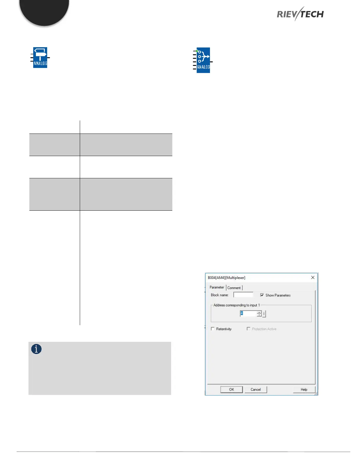
The Parameters tab contains:
BASE ADDRESS(corresponding to Input 1): Contains the
address of the INPUT 1 input.
Retentivity: Chooses whether or not the function is
reinitialized if the controller power supply is disconnected.
When they are not connected, the digital input is in the
OFF state and the WORD inputs contain 0.
Example:
When the BASE ADDRESS parameter contains the value 0
these inputs have addresses 0, 1, 2, 3 respectively, and in
 Loading...


