An icon for the simulation of a power failure, for
testing the switching response with reference to retentivity
characteristics after a power failure.
Icons (e.g. bulbs) for monitoring outputs.
Simulation control icons and
Time control icons.
Simulation control icons
Time control
If you have programmed a time-sensitive circuit, you
should use the time control to monitor the scan time of
your circuit program.
Start simulation for a specific
time or number of cycles.
Set the period and the number
of cycles using the following
icons.
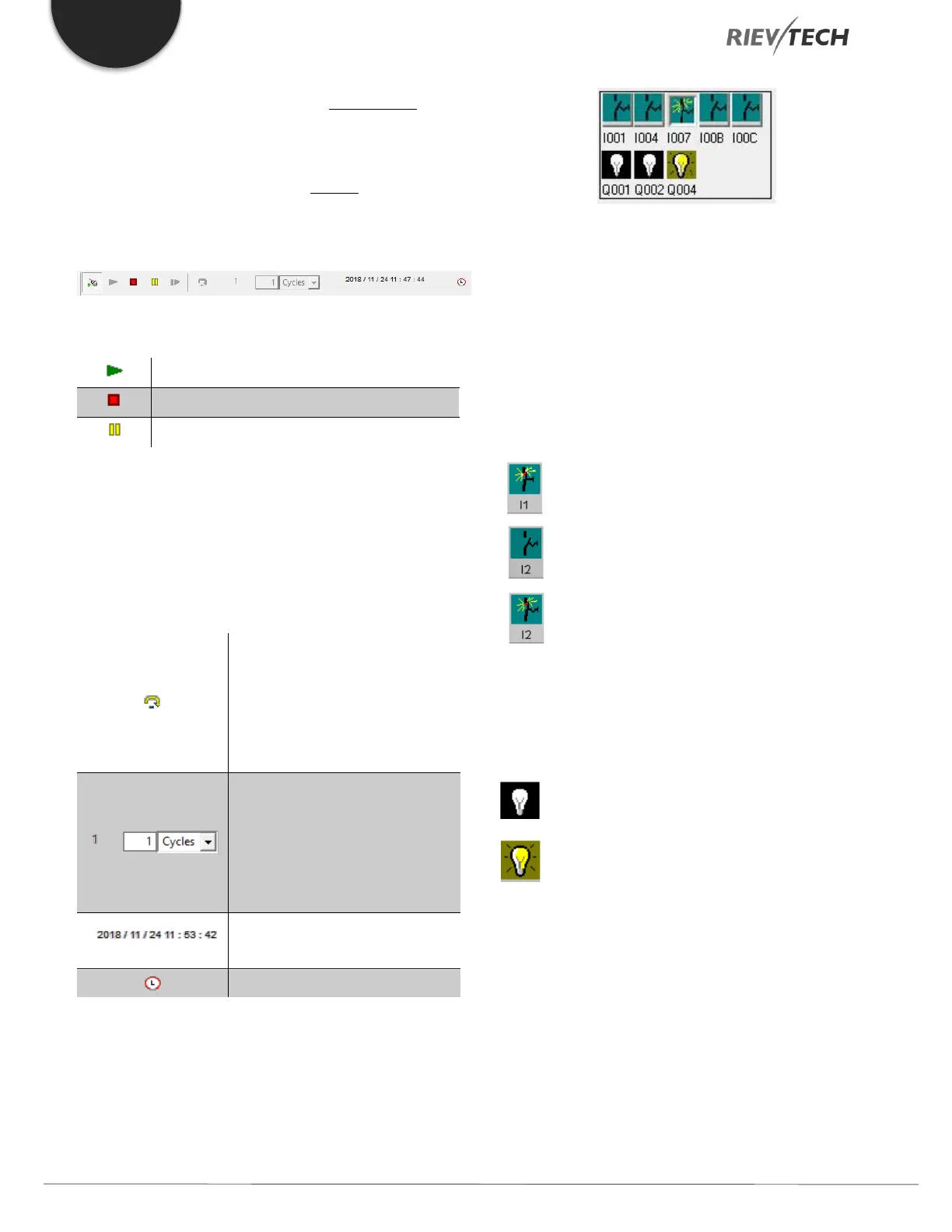
Status Display
Layout of Inputs
The inputs are displayed in the form of key or switch icons.
The name of the input is displayed below the icon. An
open input represents an inactive switch. When you click
on the icon, it is made active and the switch is shown in a
closed state.
Icon for pushbutton I1, not actuated - open input
Icon for pushbutton I1, actuated - closed input
Icon for pushbutton I2, not actuated - open input
Icon for pushbutton I2, actuated - closed input
The layout of the Outputs
The status of an output is indicated by a light or
dark bulb icon. The name of the output in your
circuit program is displayed below this icon.
Status display of output Q1 - Output switched off
Status display of output Q1 - Output switched on
The output status only indicates the status as such. Here,
you cannot switch an output by clicking on an icon. When
your circuit program switches an output, the indicator
 Loading...


