lamp is switched on; when the output is switched off, the
indicator lamp is also switched off.
Prerequisite: The display of signal states and process
variables is enabled under Tools Simulation.
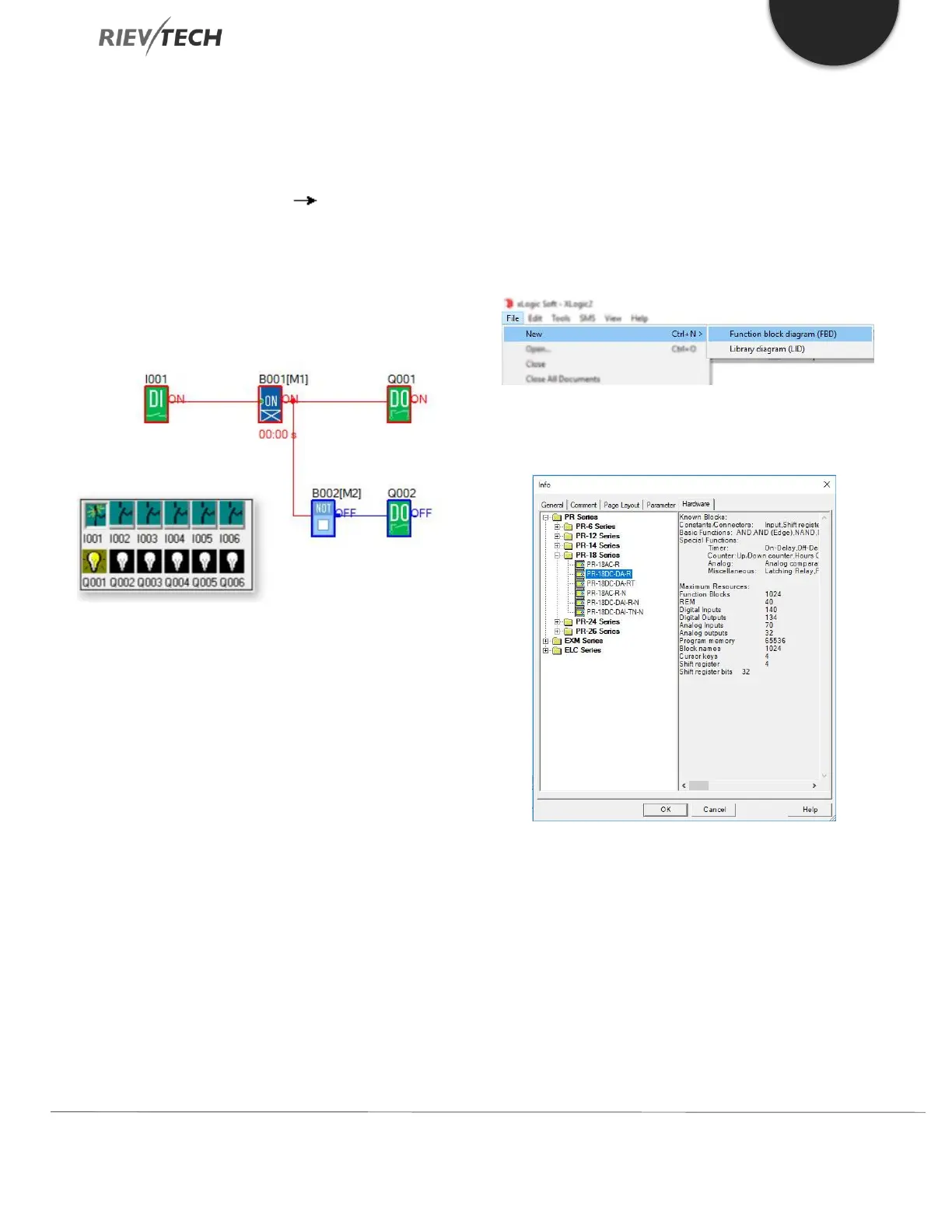
The coloured indication lets you identify the "1" or "0"
status of a connecting line. The default colour for
connecting lines carrying a "1" signal is red. The default
colour for connecting lines carrying a "0" signal is blue.
Basic Operation
This chapter will tell you how to write logic function
program with xLogicsoft, how to simulate the program
you write with xLogicsoft, how to communicate between
PC and xLogic with xLogicsoft, how to copy system
document of xLogic with xLogicsoft, and how to complete
the update of an application and system program code. If
you want to write a function block program you need to
carry out the following steps:
1. Create a new file/project
2. Add the function blocks required by your program to
the programming workspace.
3. Set the properties of the blocks added if required.
4. Link the program blocks to in a logical order that your
program requires.
5. Test your program using the Simulation mode(F3).
Create New File
To create a new file, click ‘New’ option from the ‘File’
menu. As shown in the following fig.
Select the xLogic hardware you are writing the program
logic for.
Page Layout
In the Page Layout tab, you can specify how and on
how many pages to print your logic program. You can
preview the pagination in this tab. If you choose more
than one program page, the page breaks are indicated
by white lines on the programming interface
environment.
 Loading...


