PROGRAM LOGIC REQUIRED
1. I1--IA Digital Inputs in the Master is to control the
Digital Outputs, Q1—QA, in both Slave1 and Slave2. If I1
is ON in the Master, the corresponding Q1 in the Salves
is to be ON; I2 is ON in the Master, the corresponding Q2
in the Slaves is to be ON and so on up to IA/QA. If an
input is Off in the Master, the corresponding output in
both Slaves must also be Off.
2. Read the Inputs I1--IA statuses of Slave 1 and reflect
their states in the Flags F11--F20 in the Master. Read the
Inputs I1--IA statuses of Slave 2 and reflect their states in
the Flags F21--F30 in the Master.
3. Read the AF1 flag of Slave1 and save it in the AF1 flag
of the Master. Read the AF1 flag of Slave2 and save it in
the AF2 flag of the Master.
Program in Slave 1
Note: In the program, you can put the input/output block
in, but you cannot link the input pin of the output block
as this would disable remote control of the output.
Program in Slave 2
Note: In the program, you can put the input/output block
in, but you cannot link the input pin of the output block
as this would disable remote control of the output.
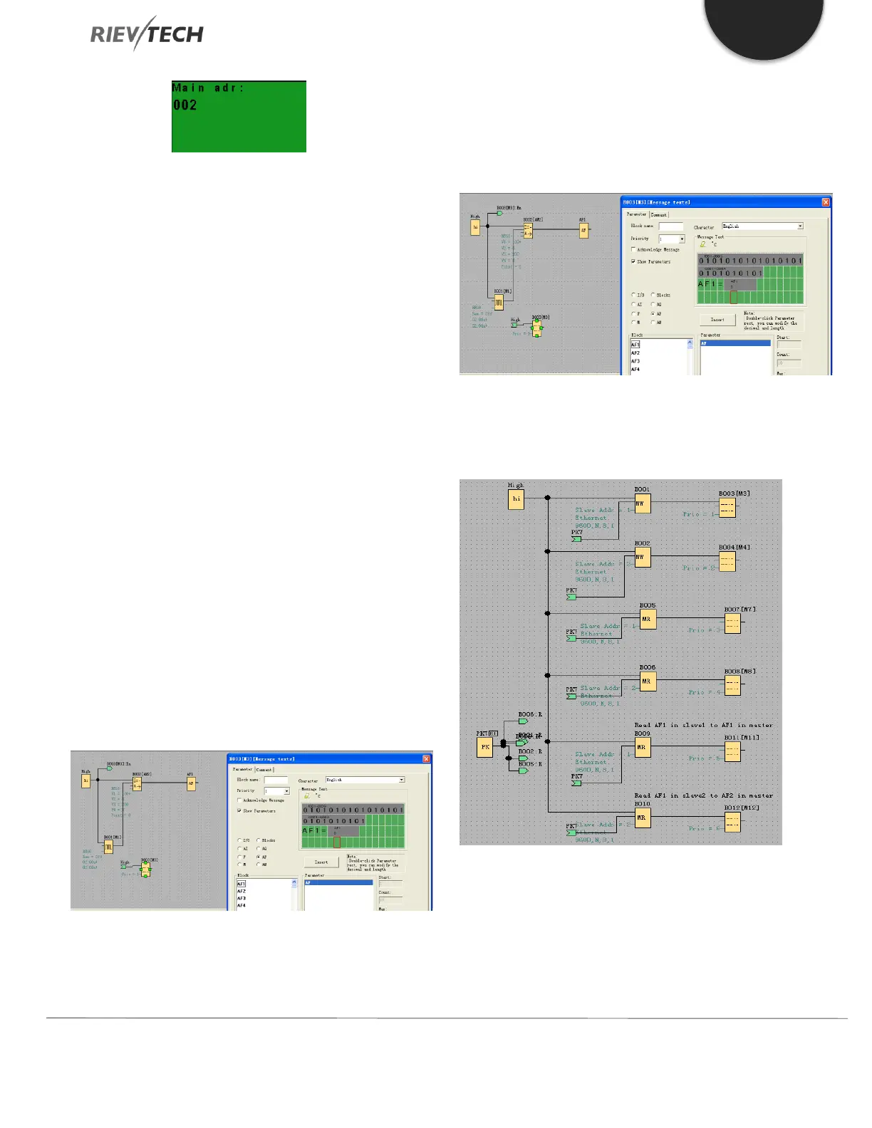
Program in Master
You need to use the MODBUS BLOCK to realize the data
transmission between Master and Slaves.
B001: Transfer the I1--IA status of the Master to the Q1-
QA of the Slave1. Settings are as follows:
 Loading...


