During business hours, if someone enters the store, the
detector B1 will trigger an electric motor to open the door,
vice versa.
At closing time, the detector B2 controls the electric motor
for a further hour to make enough time for customers to
leave.
Trigger Electric Motor for Opening the Door
The output Q1 is switched On and triggers electric motor,
when:
Manual control switch I5 is On – the door is open
all the time.
Somebody is detected approaching the door.
The door has not been opened fully – I4 limit
switch is not Off.
Trigger Electric Motor for Closing the Door
Manual control switch I6 is On – the door is
closed all the time.
Nobody is detected approaching the door.
The door had not been closed fully – I3 limit
switch is not Off.
Buzzer
Connect the buzzer to output Q3. When the door is going
to be closed; the buzzer gives off sounds for a short time
(1s in this example). To attach the buzzer, we need to
connect the following circuit program to output Q3.
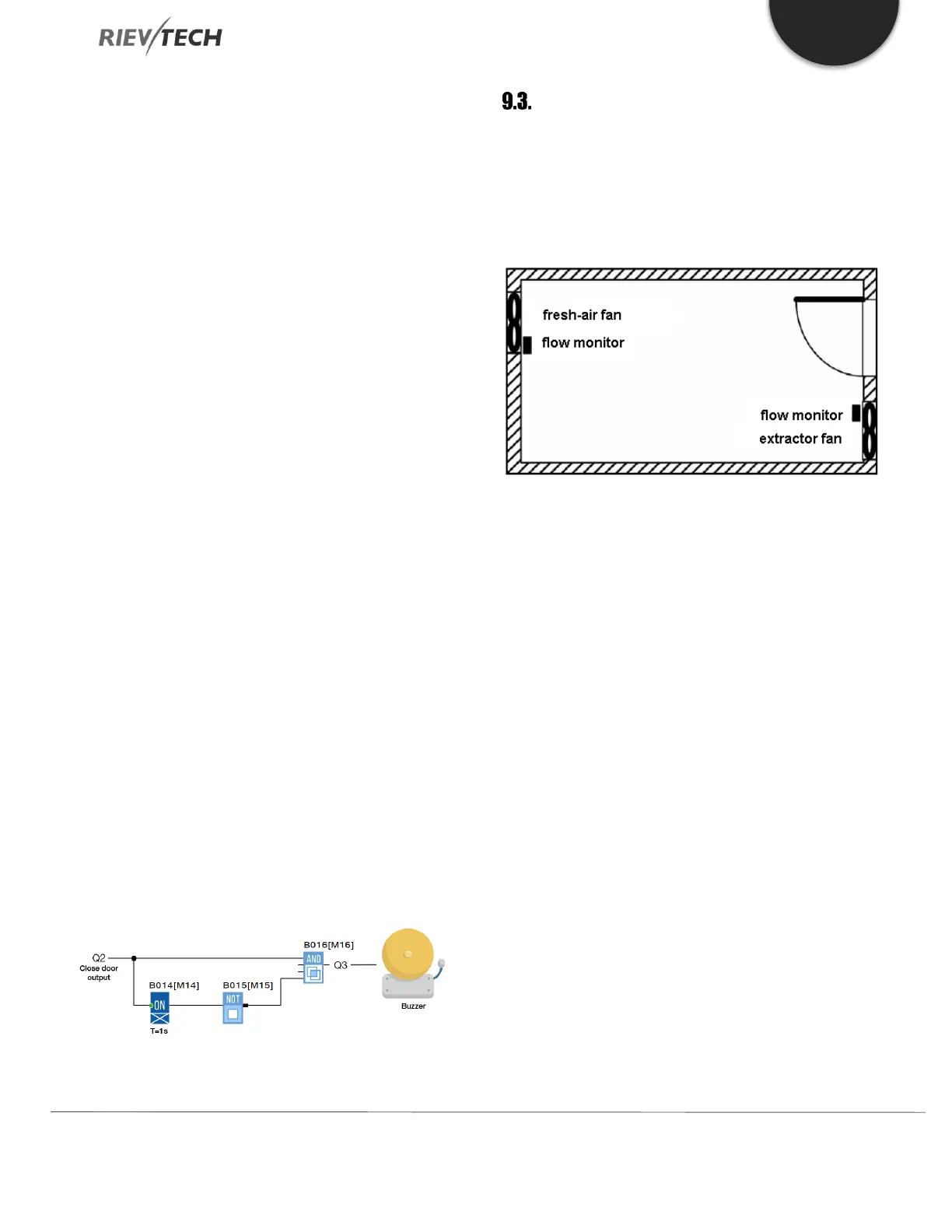
Ventilation System
Requirements for a Ventilation system
A Ventilation system supplies fresh air into a room and
exhausts the contaminated air. Let us look at the following
sample system:
A room contains an extractor fan and a fresh-air fan.
Each fan is monitored by means of a flow sensor.
The pressure in the room may rise above atmospheric
pressure.
The fresh-air fan may only be switched on if the flow
sensor signals the safe operational state of the extractor
fan.
A warning lamp indicates failure of one of the fans.
Standard Solution
The control circuit diagram of an example Ventilation
system is as follows:
 Loading...


