The fans are monitored by means of flow sensors. If no
airflow is registered after a short delay time has expired,
the system is switched off and an error message is
generated, which can be acknowledged by pressing an Off
button.
Fan monitoring requires an analyser circuit with several
switching devices, in addition to the flow sensors. A single
xLogic device can replace this analyser circuit.
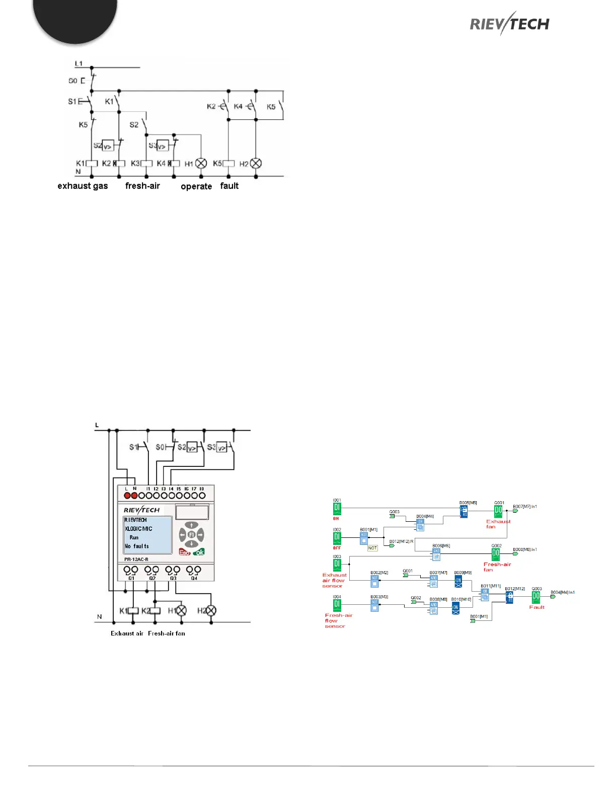
The Scheme of xLogic
The circuit diagram of a ventilation system:
Required components:
K1 Main contactor
K2 Main contactor
S0 (make contact) Off button
S1 (make contact) On button
S2 (break contact) Flow monitor
S3 (break contact) Flow monitor
H1 Flashing lamp
H2 Flashing lamp
xLogic Solution
The use of xLogic reduces the amount of switchgear. Thus,
you save installation time and space in the control cabinet.
You may even be able to use as a smaller control cabinet.
With xLogic you can also switch off the fans sequentially
after the system is switched off.
The circuit in xLogicsoft
The system is switched on and off via inputs I1 and I2. The
fans are connected to outputs Q1 and Q2. The flow
sensors are connected to the inputs I3 and I4. Blocks B07
and B10 are used to set the watchdog times. If any timer
expires, the flow sensors should send a signal to the fault
output Q3.
You can invert output Q3 to use output messages at Q4.
Relay Q4 only drops out if main power is lost or if there
is a fault in the system. The output can then be used for
a remote message.
 Loading...


