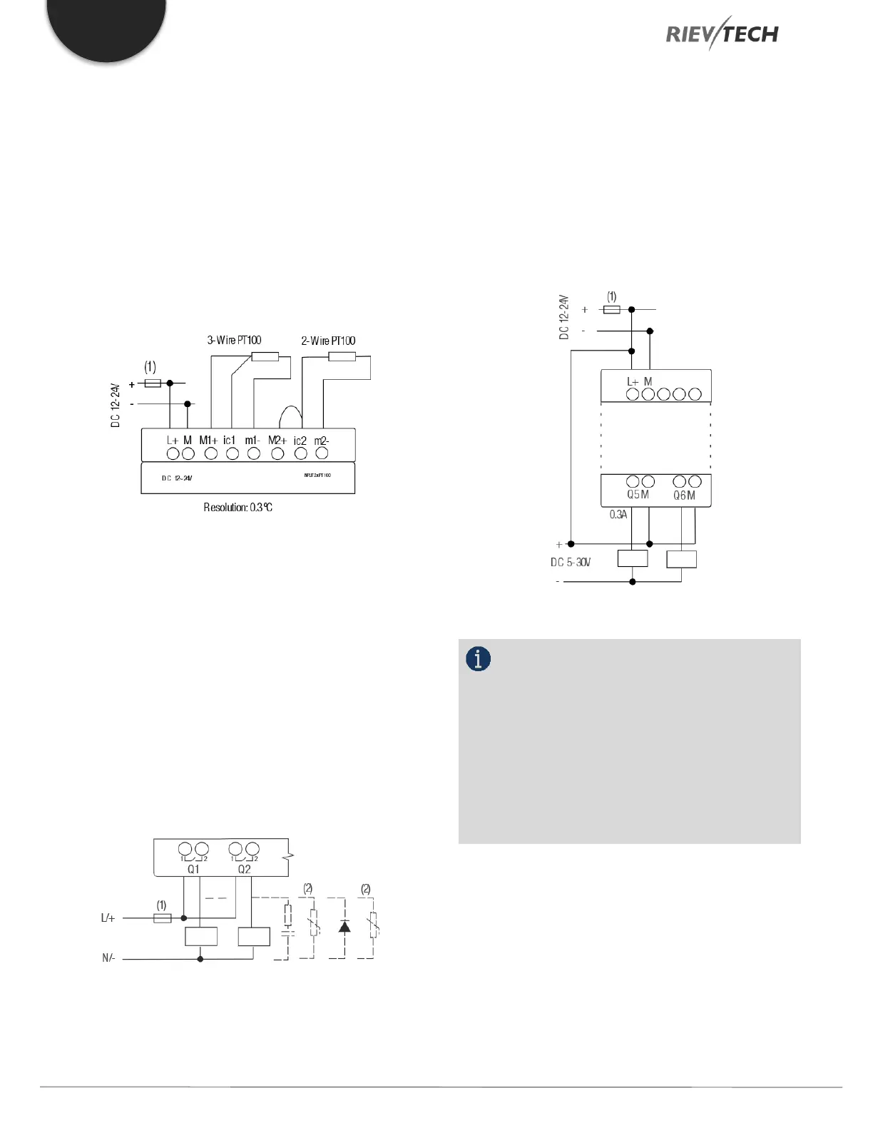
4.4.7. Analogue Input Connections (PT100)
Either 2 or 3-wire PT100 sensors can be connected.
With a 2-wire sensor, connect to terminals M1+ and M1-.
Short between M1+ and IC1. There is no compensation
for any impedance in the wire. A measurement error of 1
Ω is equivalent to +2.5 °C.
Using a 3-wire sensor can inhibit any influence caused by
cable length.
Figure 22 Analogue PT100 2-, 3-Wire Inputs
4.4.8. Connecting Output Signals
Using a Digital Output – Relay Type
Various loads such as a lamp, fluorescent tube, motor,
contactor, etc., can be connected to the relay outputs of
the Rievtech hardware. The maximum output current that
can be handled by the relay is 10A for the resistance load
and 3A for an inductive load. The relay output connection
should be wired as per the following figure:
Figure 23 Relay Digital Output
Using a Digital Output – Transistor Type
The load connected to a transistor output
must have the following characteristics:
* The maximum switching current cannot exceed 0.3A.
* When the switch is ON (Q=1), the maximum current is
0.3A.
Figure 24 Transistor Digital Output
NOTICE:
* The load connecting voltage must be ≤60 VDC
and it must be DC.
* The “+” terminal of the output wiring must be
connected to the DC positive voltage, and it must be
connected with the “L+” terminal of the CPU power
terminal. The load must be connected with the “-ve”
terminal of the DC negative voltage supply.
Using an Analogue Output
PR-E-AQ-VI (0 to 10 VDC)
 Loading...


