6.1.1. General Input and Output
Functions
Digital Input
Digital input blocks represent the physical digital input
terminals of your Rievtech CPU and expansion units if
fitted. The following table list the maximum number of
digital inputs that a CPU can support.
Table 11 Maximum Digital Inputs per CPU
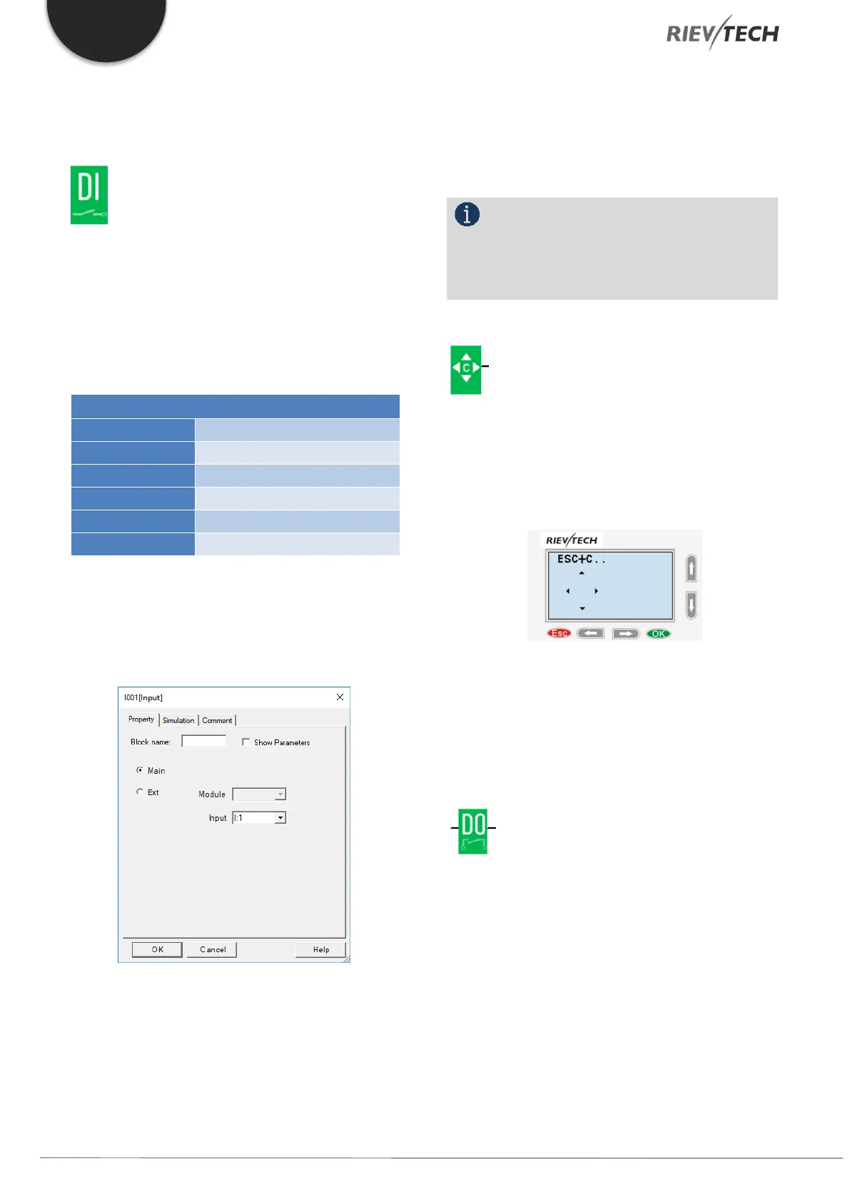
To configure a digital input block which has been placed
in your workspace, double-click on it to open the blocks
configuration options.
Figure 40 - Digital Input Block Configuration
If the input is on the main CPU then you can select it
using the Input drop-down box. Only available inputs
will be shown.
If the digital input is in an expansion module, then select
the radio button for Ext. Module and use the drop-down
box to select which expansion block number, followed
by the digital input number.
NOTICE:
I12 means digital input 2 on expansion
address 1, I81 means digital input 1 on expansion
address 8.
Cursor keys
Up to four cursor keys are available to you. Cursor keys
are programmed for the circuit program in the same
way as other inputs. Cursor keys can save switches and
inputs and allow operator control of the circuit program.
Switch the screen to the current page (above shows) by
pressing the Left or Right key, and press ESC key and
arrow keys at the same time, then the corresponding
cursor keys will turn on and give off a high trigger!
Digital Output
Output blocks represent the output terminals of xLogic.
You can use up to 2 outputs (ELC-6), 4 outputs (PR-
12),70 outputs (PR-18), 72 outputs (PR-22), 74 outputs
(PR-26). In your block configuration, you can assign an
output block to a new terminal, provided this terminal
is not already used in your circuit program.
The output always carries the signal of the previous
program cycle. This value does not change within the
current program cycle.
 Loading...


