and select the corresponding sensor type for DC0.10V,
0/4.20mA or PT100 input.
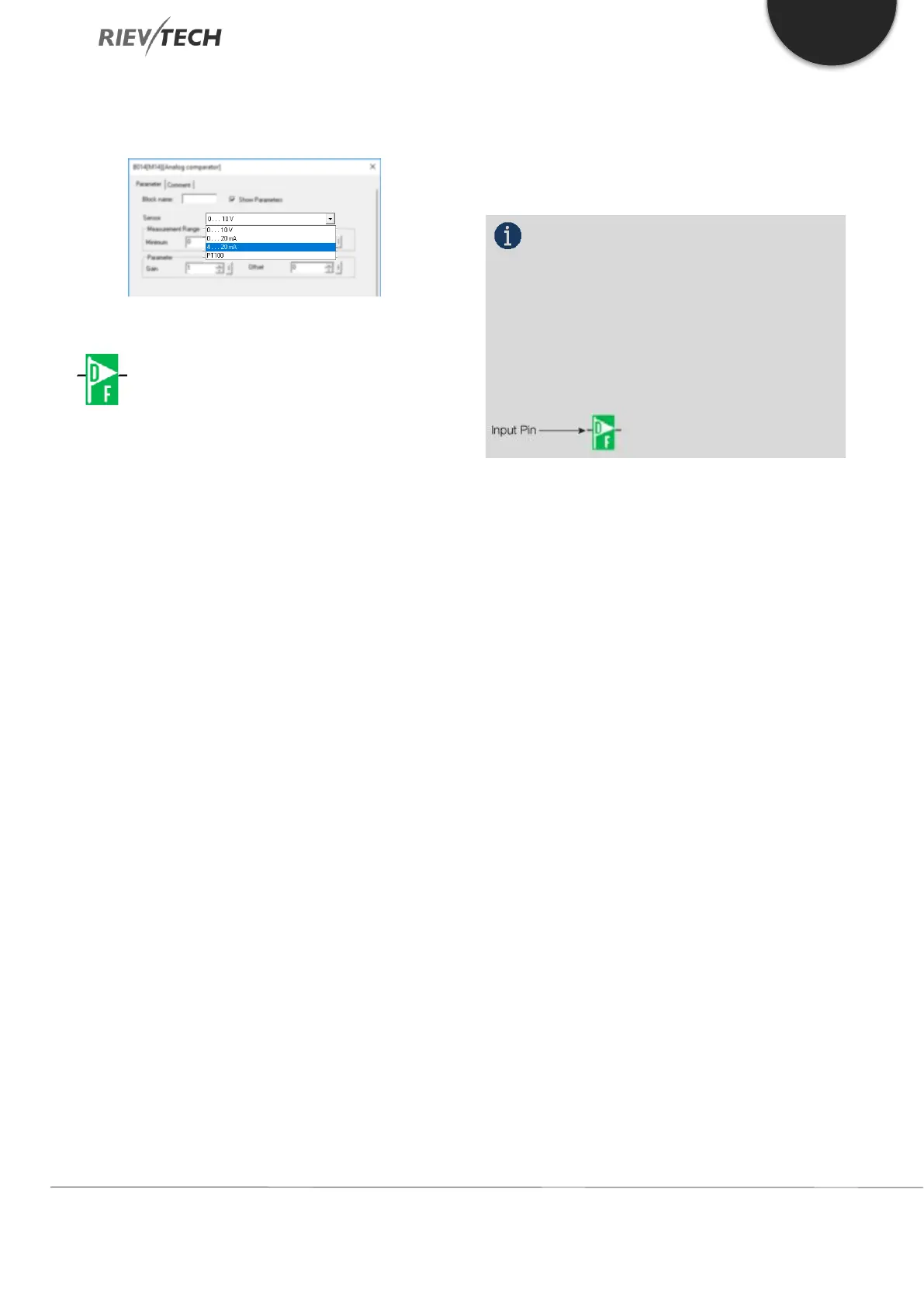
F (Digital Flag)
Flags are used when xLogic works in a communication
system. F is a digital flag which is used to save /transfer
signal 1 or 0 (data format is Bit) and AF is an analogue
flag which is used to save /transfer analogue values
(data format is Signed short) between the master and
slave devices. Up to 32 (ELC-6), 128 (PR-12/ELC-22/ELC-
26) can be used when programming. In your block
configuration, you can assign a new number to the flag,
provided this flag number does not already exist in your
circuit program.
The output always carries the signal of the previous
program cycle. This value does not change if the
communication has failed.
Start-Up Flag: F8
The F8 flag is set in the first cycle of the user program
and can thus be used in your circuit program as a start-
up flag. It is reset after the first program execution cycle.
In the subsequent cycles, the F8 flag reacts in the same
way as the F1 to F64 flags.
Backlight Flag: F64
The F64 flag controls the backlight of the xLogic display
or the ELC-43T backlight. You can use the outputs of
timers, message texts, or other function blocks to
activate the backlight flags. To enable multiple
conditions to control the backlight of the devices, you
can use multiple function blocks in parallel or in
sequence. Buzzer of ELC-43TS control flag: F63
NOTICE:
1. The address of “F“ can be found in the
Modbus communication protocol file. The F block
figure must have the input pin in the xLogic showing.
2. Keep the input pin of F NULL (do not
connect with other blocks) if you want to use the write
property.
 Loading...


