The CPU will upload the AF1 to AF3 values to the
server (Slave ID 1) as follows:
00 01 00 00 00 0D 01 10 00 00 00 03 06 00 64 03 E8 27 10
The request and response are prefixed by six bytes as
follows:
byte 0: transaction identifier - copied by server
byte 1: transaction identifier - copied by server
byte 2: protocol identifier = 0
byte 3: protocol identifier = 0
byte 4: length field (upper byte) = 0 (since all
messages are smaller than 256)
byte 5: length field (lower byte) = number of bytes
following
byte 6: unit identifier (previously ‘slave address’)
byte 7: MODBUS function code
byte 8: Register of the slave start address
byte 9: Register of the slave start address
byte 10: number of registers
byte 11: number of registers
byte 12: data length field (lower byte) = number of
bytes following
So, AF1 = 00 64 (DECIMAL 100)
AF2 =03 E8 (DECIMAL 1000)
AF3 = 27 10 (DECIMAL 10000)
The server end(slave1) responds
00 01 00 00 00 06 01 10 00 00 00 03
So, if the "Trg" input remains high, then the output
will be high also after the CPU gets the above, correct
response.
NOTICE:
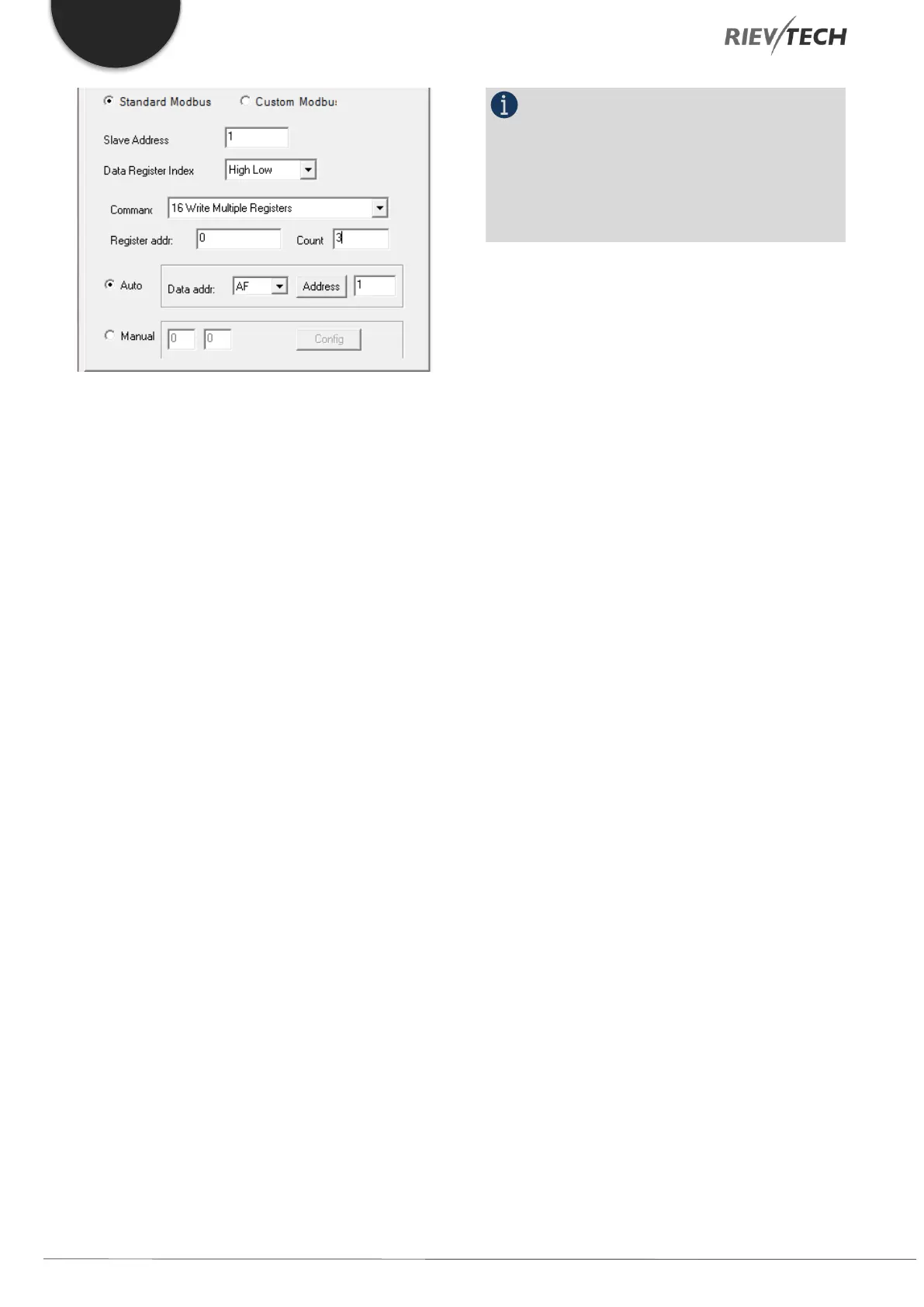
The Modbus Function Code 16 is used to upload
analogue values (inputs, outputs, flags and REG) and
Modbus Function Code 15 is used to upload digital
values (inputs, outputs and flags).
 Loading...


