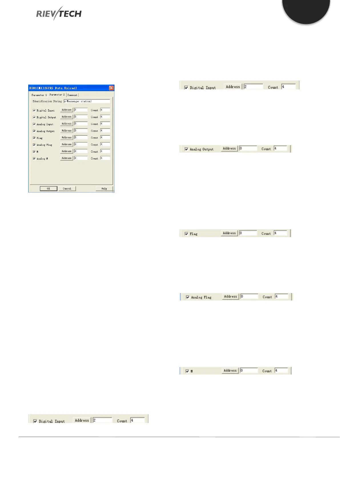
b. Custom Modbus
Using this setting enables you to upload a mix of data
types as configured under the Parameter 2 tab of this
block.
The above example would result in the following data
being uploaded to the server:
00 09 00 00 00 4c 01 8b 49 14 78 2d 4d 65 73 73 65 6e 67
65 72 20 73 74 61 74 69 6f 6e 31 01 01 01 02 01 0d 0b 08 00
80 00 88 00 00 00 00 0c 08 00 00 00 00 00 80 00 88 16
01 02 17 08 01 c2 00 00 02 26 00 00 07 01 04 0d 08 00 00
00 00 00 00 01 c2
Explanation of the data message:
00 09 00 00 00 4c – Modbus/TCP prefixed data of six
bytes
01 – CPU address (Default is 1)
8b – Upload code (Fixed if GPRS Data Upload used)
49 – Length field (Number of bytes following)
14 – Length field (Number of bytes of identification
string)
78 2d 4d 65 73 73 65 6e 67 65 72 20 73 74 61 74 69 6f
6e 31 – CPU Station 1 (Identification string)
01 – Type Code (01=Digital Inputs)
01 – Length field (number of bytes of digital inputs)
01 – Status of digital inputs (I3=1, I4=0, I5=0, I6=0)
01 – Type Code (02=Digital Outputs)
01 – Length field (number of bytes of digital inputs)
0d – Status of digital outputs (Q1=1, Q2=0, Q3=1, Q4=1)
0c – Type code (0c means the Analogue output)
08 – Length field (number of bytes of the analogue
outputs)
00 00 00 00 00 80 00 88 – Analogue output values
(AQ1= 00 00, AQ2 = 00 00, AQ11= 00 80, AQ12= 00 88)
16 – Type code (16 means the digital flag)
01 – Length field (number of bytes of the digital flag)
02 – Status of the digital flag (F1=0, F2=1, F3=0, F4=0)
17 – Type code (17 means the Analogue flag)
08 – Length field (number of bytes of the analogue flag)
01 c2 00 00 02 26 00 00 – Analogue flag values (AF1=
01 c2, AF2 = 00 00, AF3= 02 26, AF4= 00 00)
07 – Type code (07 means the M status)
01 – Length field (number of bytes of M(Function block
status(1/0))
 Loading...


