Programmable Relay ● User Manual for ELC, EXM and PR Series 84 2020 v6.0 ● © Rievtech Co.,
Ltd. ● www.rievtech.com
04 – Status of the M Flags (M1=0, M2=10, M3=1, M4=0)
0d – Type code (0d means the AM value)
08 – Length field = number of bytes of AM
00 00 00 00 00 00 01 c2 – AM values (AM1=00 00,
AM2=00 00, AM3=00 00, AM4=01 c2)
The expected server response would be:
00 00 00 00 00 02 01 8b
So, if the Trg input is kept High, then the output, Q, will
be kept High is the above correct response is received.
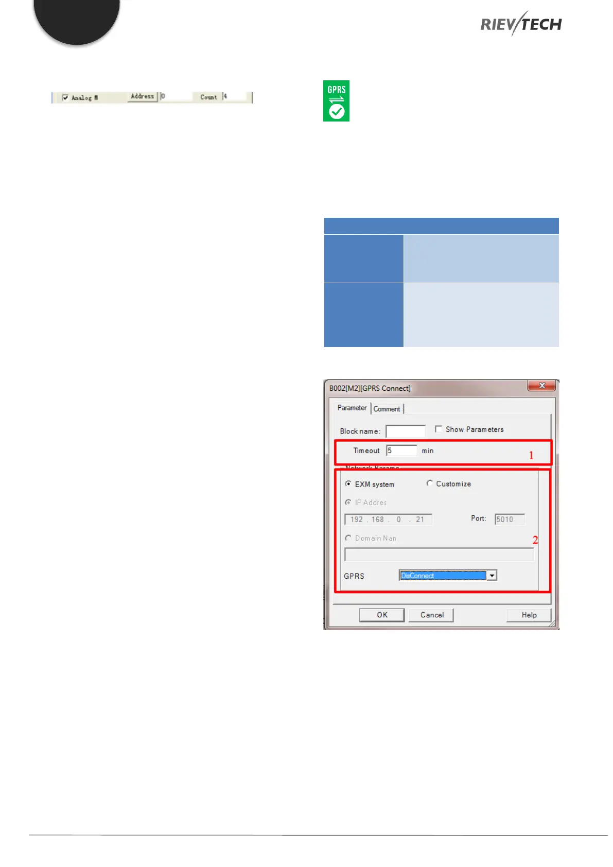
GPRS Connect
Description of Function
The block can be used to enable/disable the GPRS
connection of the CPU.
When the trigger input is
enabled, the GPRS connection is
enabled.
The output Q is switched On
once a GPRS connection is
established. It will be set to Off if
the connection is disconnected.
Configuration of Function
1. Timeout Setting – This is the length of time for
the timeout if there is no data transmission
during this period. The GPRS will disconnect
automatically.
2. Network Params – There are two options to
choose from.
a. EXM System
If this setting is selected, the IP and port number of
the server shall be the same as configure in the menu
option… ”SMS…Set GPRS Params”.