Copyright © 2008 by Lucky Distributing Revision 2.0 updated 11/05/2008
8
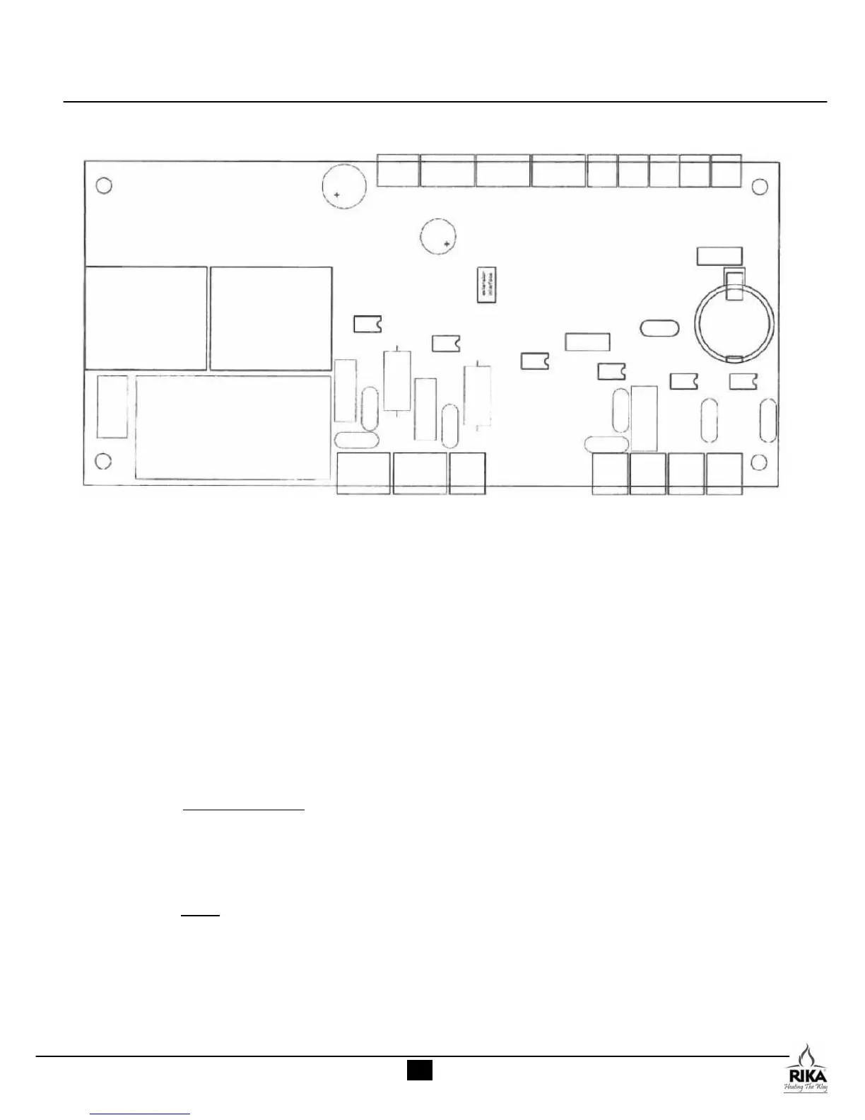
MAIN CONTROL BOARD
1 2 3 4 5 6 7 8 9
AC Voltage Side
I 110VAC 60Hz
II Combustion Fan
III Convection Fan
IV Ignition Element
V Auger Motor
VI Open
VII Reserved
NOTE: A common error made when swapping out a
control board is to cross the auger motor and igniter leads.
A symptom of this is the auger motor turning continually
with no pause for the 12-minute duration of the ignition
element time, resulting in a very full burn pot. The igniter
will pulse on and off during the same period.
DC Voltage Side
1 HAL-IC Combustion Motor Regulator
(silver
bullet looking item mounted just above the air intake tube.
There is another lead on this component that is also attached
to the combustion fan).
2 User Control Interface
3 Optional Remote Thermostat
(leave open if no thermostat present)
4 Air Sensor
5 Low Limit Sensor
(error flashing immediately following startup cycle may
indicate a disconnected lead or a failure of this
component. Other possible triggers are a first-time-fill
of the hopper, open hopper lid or recent empty hopper
– restart stove to see if error recurs).
6 High Limit Sensor
(error flashing during
startup cycle may indicate a
disconnected lead or a failure of this component)
7 open
8 open
9 open
I II III IV V VI VII