Temperature controlling parameters: ST, F01,F02.
ST: is stop temperature that can be adjusted by SET key directly.
is the high limit of setting temp.
These two parameters is used to limit the setting temp range in
order to avoid misoperation.
F01: is the low limit of setting temp.
F02:
F01≤ST≤F02
1.2.1Heating status description
RINGDE R
R
D
R
RINGDER
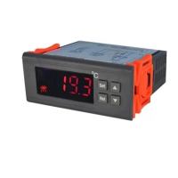
RC-113M
Top Runner in Temperature Measuring and Controlling Industr y
PID Temperature
Controller for Heating
User Manual
WEB: WWW.RINGDER.NET
Product Introduction
Xuzhou Ringder Electrical Equipment Co., Ltd.
Tel: 86-516-66656756 /87764448 FAX: 86-516-87769006
Website: http://www.ringder.net/indexen.asp;
http://ringder.en.alibaba.com/
Address: No. 385, Zhongshan North Road,Gulou District,Xuzhou City,Jiangsu Province, China.
E-mail:xzringder@outlook.com
Product Introduction
This model is specially designed for elaborate heating
system, which adopt high accuracy temperature sensor,
PID control, minimum temperature inertia, very high
control accuracy(0.1C within normal temperature
period).
RC-113M PID temperature controller is widely applied to
various equipments and places that need to control
temperature accurately, such as incubator, Heating
equipment in the laboratory etc.
Technique Specification
Anycontrol basic technique :specification list
Power supply
Rated power
≤1. 5W
Load capacity
Sensor type
NTC, 25℃/50KΩ
Protection class
IP65
Work or storage -10~60℃, RH<90% no condensation
Temp. range
-40~110℃
Environment
Comply with environmental standards
Wire length
Communication: 1Km,sensor:100m
220VAC±10% 50HZ
110VAC±10% 60HZ(optional)
≤ 1500W; 110V/60HZ/750W;
≤10A/220V/50HZ/2000W; 110V/60HZ/1000W(optional).
5A/220V/50HZ/
Function and Parameter
F01
-10~Set temp.
-10
F02
Set temp.~100
100
F03
-7~7
0.0
Code
Function
Setting Range
Default
Unit
Set Low Lim it
Set High Li mit
Calibra tion
1.1.1 Temperature calibration
1.1 Temperature measurement
When there is some difference between the measuring
temperature and the real temperature, the difference can be
calibrated by menu F3, and calibration method should follow
the below formula:F3=real temperature-measuring
temperature. Other functions will execute according to the
calibrated temperature value.
1.1.2 Sampling period
The sampling period of this model is 1 second fixedly, and other
sampling period can be customized.
1.2 Temperature control
The controller can PID adjust the power of the heater, and make
the temperature constant around the setting temp. During
25~42℃, the accuracy can be 0.1℃.
Product Size
Wiring Diagram
Load
Power
Sensor
Connect the wires strictly according to the diagram, the voltage
must within 220VAC±10%.
The current of the load must: inductive load or filament lamp≤
10% of the current on the wiring diagram; resistive load≤60% of
the current on the wiring diagram.
Assembly and Installation
Warning:
Relative humidity> 9 0 % ,have condensation
Strong vibration or struck
The places that temperature<-10℃ or>6 0℃ ;
Exposed to the continuous water mist spraying;
The places that have inflammables and explosives;
Exposed to the dust;
The controller must be connected by trained electricians
according to the user manual strictly, and avoid installing in the
below environments:
Wireless electromagnetic interference or strong magnetic
fields(near to transmitting antenna or switch board room);
2.1 Assembly
Exposure to corrosive and pollution gas (for example:the gas,
smoke or salt fog that contain sulfur or ammonia;
2.2 Please install the controller according to the following
Cut out a hole at the installing postion:7 1 * 2 9mm
Detach the slide fasteners, and put the controller into the hole.
(1st step,Figure2.a);
Install the faterners;
(2nd step,Figure2.b);
Figure2.a
Figure2.b
After connecting the wire, install the waterproof tailgate
(3rd step,Figure2.c);
Figure2.c
How to disassemble the controller from the hole?
Firstly disassemble the
tailgate, then press the
position(Figure2.d)
sliding backwards to
disassemble the controler;
Figure2.d
User Interface & Button Function
3.1 Display Area
220V/50 HZ
No.
Meaning
Working Status
/
/
/
1
2
3
Please
refer to
Display
Not Displ ay
Flash
Set Indic ator
Heat Equi pment
Alarm
Non set sta tus
Work status
Set statu s
Stop stat us
Alarm sta tus
Non alarm s tatus