Do you have a question about the Rinnai EHPS265VM and is the answer not in the manual?
System installation must comply with AS/NZS standards and manufacturer's instructions.
Installation, commissioning, servicing, and removal must be done by licensed tradespeople.
Not suitable for spa/pool heating or hydronic applications; general warnings.
Mandatory use of licensed tradespersons for installation and service.
Do not tamper with or remove safety devices; ensure they are fitted and working.
TPR valve must be fitted and its drain pipe never sealed or blocked.
Use provided handholds for moving and positioning the unit.
R290 is flammable; handle with appropriate license and precautions.
Use standard 230V AC, maintain voltage/frequency within limits, and ensure sinusoidal waveform.
Do not tilt more than 45° from vertical to prevent compressor damage.
Store and transport in areas without ignition sources due to flammable refrigerant.
Unpack, check for damage, and verify all components are supplied before installation.
Micro-channel heat exchanger and cylinder sensor control heating operation.
Includes start-up delay, defrost function, and safety cut-outs for pressure/temperature.
Designed for outdoor residential use, factory preset to 60°C.
Ambient temperature limits for heat pump and element operation.
Outlet water temperatures and storage capacity details.
COP, heat pump output/input, electric element rating.
IP rating, sound pressure, power supply, weight, refrigerant type/mass.
Visual representation of unit dimensions and key ports.
Details for hot/cold inlet, TPR, and condensate connections.
Performance metric for heating water at specified conditions.
Ensure location complies with AS/NZS 5149 for flammable refrigerant.
Place unit near frequently used outlets to minimize hot water delay.
Requirements for internal installation, including ventilation and room volume.
Avoid areas below windows, blocked vents, or near corrosive environments.
Consider local noise regulations and placement relative to neighbours/bedrooms.
Position for sufficient air supply and control interface accessibility.
Ensure vertical position and clear access to all components and rating plates.
Install on a level, stable base capable of supporting the unit's weight.
Provide snowfall protection for air outlets in areas with heavy snow.
Minimum 600mm discharge, 150mm suction side for fan airflow.
300mm vertical and 500mm front clearance for servicing and anode access.
Comply with G12/AS1, AS/NZS 3500.4; allow room for service access.
20mm inlet, fit drain tap; use pressure-reducing valve if pressure exceeds rating.
Plumb condensate to drain/gully trap using 19mm tapered connection.
Ensure TPR valve is installed correctly for safe operation and downward water flow.
Fit a drained safe tray for potential leaks as per standards.
Installer responsibility to size pipes for performance and supply pressure.
Adequately support unit against earthquake forces per NZBC B1.3.2.
Schematic showing water inlet, valves, and connections.
Condensate drain line requirements and restrictions.
Automatic cycle heats water to 70°C to prevent legionella bacteria.
Prevent scalding by limiting delivered temperature for personal hygiene fixtures.
How to initiate a manual disinfection cycle via the controller.
Meet NZ drinking water standards and Aesthetic Values.
Water quality outside specified limits voids warranty.
Filtration, stagnation prevention, and bore/tank water considerations.
Electrical work must be done by a qualified person per AS/NZS 3000.
Connect via 15A plug, use independent supply with isolating switch.
Guidelines for performing insulation tests on electronic components.
Diagram showing electrical connections for all components.
Key for identifying wire colors used in the diagram.
Functions of On/Off, Return, Escape, and Lock/Unlock buttons.
Accessing and viewing operating modes via the 'M' button.
Using Up/Down buttons to change temperature settings.
Using button combinations for boost, defrost, ventilation, and recovery.
Interpreting LED status for heating, Wi-Fi, defrost, and errors.
Description and settings for different operating modes.
Using electric heating only or a one-off heat boost.
Activating or deactivating the forced defrost feature.
Step-by-step guide to setting the system clock.
Setting on/off timers, including weekday and daily cycles.
Procedures for filling the system with water and draining it.
Steps to safely turn off the heat pump system.
How the system operates upon first power-up and heat-up cycle.
Checks for water presence, wiring, earthing, voltage, and airflow.
Explain system use, care, and provide installation guide to the customer.
List of error codes and their possible causes for the controller.
Details on LED indicators for system faults, for service personnel.
How to enter the parameter query menu using controller buttons.
Explanation of parameter numbers, names, and their values/states.
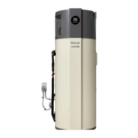
The Rinnai Enviroflo Hot Water Heat Pump is a hot water system designed primarily for residential outdoor installations, though internal installation in unoccupied, well-ventilated spaces is possible, provided it meets AS/NZS 5149 requirements for flammable refrigerants. It is not suitable for spa, swimming pool, or hydronic applications. The system uses R290 (propane) refrigerant, a flammable gas, and must be handled by licensed refrigeration mechanics.
The Enviroflo operates as a heat pump, utilizing a highly efficient micro-channel heat exchanger wrapped around an inner cylinder. A temperature sensor within the cylinder controls the heat pump's operation to maintain a suitable water temperature. In ambient weather conditions unsuitable for heat pump operation, an electric element provides backup heating to ensure a continuous supply of hot water. The system is factory preset to 'Standard' mode, continuously heating water to 60 °C.
The heat pump includes an electronic expansion valve (EEV), an evaporator, filters, a high-pressure switch, a 4-way valve, and a compressor. Air is drawn in through the air intake and discharged through the air outlet. The system also features three anode rods, a temperature sensor sleeve pipe, a water temperature sensor, and a heating element.
The device is controlled via a display and control panel.
| Model | EHPS265VM |
|---|---|
| Heating Capacity | 26, 500 BTU/h |
| Cooling Capacity | 25, 000 BTU/h |
| Refrigerant | R410A |
| Power Supply | 208/230V, 1 phase, 60Hz |