CAUTION
Do not touch any other areas on the PC board
besides the “SW” switches while power is
supplied to the appliance. Parts of the PC
board are supplied with 120 volts AC.
1. Turn off the gas supply.
2. Turn off the 120 V power supply.
3. Remove the front panel from the appliance.
4. Turn on the 120 V power supply.
5. Check the gas type using the data plate on
the side of the unit and parameter setting
10 (refer to Parameter Settings section).
(A=LPG, b=NG).
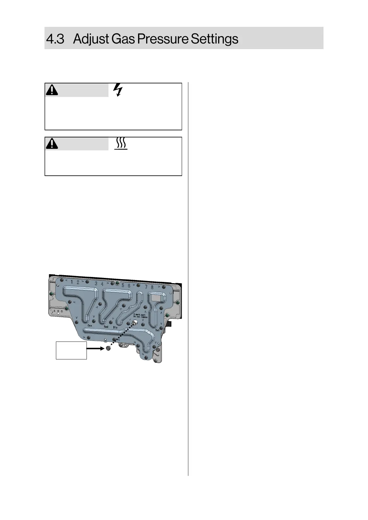
6. Remove test port screw and attach the
manometer to the burner test point, located
on the manifold.
CAUTION
Do not touch the areas at or near the heat
exchanger or hot water lines. These areas
become very hot and could cause burns.
Complete this section for high altitude installation or after converting for gas type.
Confirm that the inlet gas pressure is between the minimum and maximum pressures allowed for this
appliance.
7. Turn on the gas supply.
8. Flow water through the water heater at
the maximum flow rate obtainable. (At
least 3 gallons per minute is recom-
mended. If there is not enough water
flowing, the water heater could shut off
or sustain damage due to overheating.)
9. Push and hold “B” button. “IF” will ap-
pear on the display.
10. Push and hold “A” button. “FL” (Forced
Low) will appear on the display.
11. Push and hold “A” button again.
“FH” (Forced High) will appear on the
display.
12. While in “Forced Low” or “Forced High”,
use the Up button on the controller to
increase the pressure. Use the Down
button to decrease the pressure.
13. To exit “Forced Low” or “Forced High”,
push and hold “B” button. “2L” will ap-
pear on the display.
14. Push and hold “B” button again. “3C”
will appear on the display. (Indoor mod-
els only).
15. Push and hold “B” button again. “4t” will
appear on the display.
16. Push and hold “B” button again. The set
temperature will appear on the display
(indoor models only).
17. Close hot water taps.
18. Turn off the gas supply and 120 V pow-
er supply.
19. Remove the manometer and re-install
the test port screw (Figure 15).
20. Turn on the gas supply and 120 V pow-
er supply.
21. Operate the unit and check for gas
leaks.
22. Install the front panel.
Figure 15
Test Port
Screw
 Loading...