Do you have a question about the Rinnai SG175 and is the answer not in the manual?
Read all instructions before operating. Follow precautions for safety and performance.
Details certification by SAI global and adherence to local installation regulations.
Mandates installation by a licensed person from the Victorian Building Authority.
Covers hazards related to power cords, hot pipes, flammable materials, and pump operation.
Warns about scalding risks, especially for children and the infirm, and recommends tempering valves.
Do not tamper with or remove safety devices; ensure all are fitted and working.
Describes the PTR valve's function, normal operation, and potential issues.
Explains the ECV's function and recommended maintenance for preventing leaks.
Outlines steps to switch off electric and gas boosted systems for safety.
Addresses issues like excessive consumption, incorrect sizing, and valve problems.
Guides on checking booster operation for electric and gas systems.
Explains how to check and adjust booster thermostat settings for electric systems.
Covers usage patterns, tariffs, controller settings, and lack of solar gain.
Addresses issues related to the solar control unit being switched off or sensor placement.
Checks for restrictions in hot tap flow or cold water supply issues.
Covers broken tubes, condensation in collectors, and noisy collectors.
Addresses issues with the solar pump operating continuously and water hammer.
Explains frost valve operation and water release from collectors.
Details specifications for cylinder types, controllers, and solar collectors.
Explains the function of the variable speed pump for flow rate control.
Provides potential solar output and frost protection information.
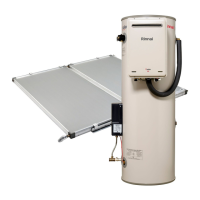
Lists dimensions and specifications for various glass-lined gas boosted cylinder models.
Illustrates connection points and dimensions for glass-lined gas boosted cylinders.
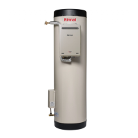
Lists dimensions and specifications for glass-lined electric boosted cylinder models.
Illustrates connection points and dimensions for glass-lined electric boosted cylinders.
Lists dimensions and specifications for stainless steel gas boosted cylinder models.
Illustrates connection points and dimensions for stainless steel gas boosted cylinders.
Lists dimensions and specifications for stainless steel electric boosted cylinder models.
Illustrates connection points and dimensions for stainless steel electric boosted cylinders.
Details boost capacity, flow rates, and consumption for various gas booster models.
Highlights incompatible models and essential usage guidelines.
Covers installation requirements, manual lifting, working at heights, and suitability.
Specifies accessibility, clearances for service, and collector positioning for optimum benefit.
Details placement of the storage cylinder for optimal hot water delivery and stability.
Provides guidelines for gas booster outdoor installation and mounting clearances.
Details gas supply requirements, pipe sizing, and isolation valve fitting.
Specifies electrical connection requirements for qualified persons and local regulations.
Covers preset temperatures for gas boosters and thermostat settings for electric systems.
Details pipe material, insulation requirements, and frost protection.
Provides guidance on pipe sizing for solar flow and return pipes based on collector type.
Discusses water pressure, chemistry, and the need for filters if impurities are present.
Refers to controller manual for information on pumped frost protection.
Lists supplied valves and fittings such as PTR valve, non-return valve, and air bleed valve.
Details valves and fittings to be supplied by the installer, including ECV and tempering valves.
Illustrates a plumbing setup with temperature limiting device and ECV.
Shows an alternative plumbing setup with temperature limiting device and ECV.
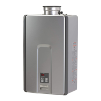
Provides information on the Rinnai Smartstart continuous flow gas booster.
Highlights tempered water requirements and local regulation compliance.
Details required clearances for gas booster flue terminals based on AS/NZS 5601.
Provides step-by-step instructions for mounting the gas booster bracket.
Illustrates component layout for SG175/SG215 with SGPKIT2C.
Lists components supplied with SG175/SG215 cylinders and SGPKIT2C.
Illustrates component layout for SG270SL/SG320SL with SGPKIT3C.
Lists components supplied with SG270SL/SG320SL cylinders and SGPKIT3C.
Illustrates component layout for Stainless Steel Gas Boost with USKIT1C.
Lists components supplied with Stainless Steel Gas Boosted cylinders and USKIT1C.
Illustrates component layout for Glass Lined Electric Boosted Systems with SEPKIT.
Lists components supplied with Glass Lined Electric Boosted Systems and SEPKIT.
Illustrates component layout for Stainless Steel Electric Boosted Systems with USKIT1C.
Lists components supplied with Stainless Steel Electric Boosted cylinders and USKIT1C.
Position and install solar collectors and the storage cylinder according to manual guidelines.
Connect the PTR valve and mount the gas booster as per instructions.
Connect pump assembly and configure the solar controller.
Connect sensor leads correctly to ensure proper system function and avoid issues.
Connect cold water supply, purge lines, and fit relief drain lines.
Connect hot water discharge and gas supply to the booster.
Steps for filling the system with water, including air bleeding and leak checks.
Ensures sensors are connected and details flow rate adjustment for optimal performance.
Checklists for solar collector installation, roof integrity, and sensor connections.
Steps for commissioning the gas booster, including gas supply, pressure, and temperature checks.
Wiring diagrams and instructions for connecting standard controllers to elements.
Specifies thermostat settings for single and twin element heaters for safety and durability.
Wiring diagrams and connection instructions for deluxe controllers.
Final steps including removing covers, activating power, and confirming temperatures.
Procedure for draining the system, including disconnecting pipes and outlets.
| Type | Tankless Water Heater |
|---|---|
| Fuel Type | Natural Gas or Propane |
| Maximum BTU Input | 175, 000 BTU/hr |
| Weight | 50 lbs |
| Energy Factor | 0.82 |
| Ignition System | Electronic Ignition |
| Temperature Range | 98°F to 140°F |
| Electrical Requirements | 120V, 60Hz |
| Vent Material | Stainless Steel |
| Ignition Type | Electronic |
| Venting Type | Direct or Power Vent |
| Minimum BTU Input | 15, 000 BTU/hr |