This document outlines the sealing methods for the C510, C520, and C527 devices, focusing on ensuring the integrity of calibration settings and preventing unauthorized access. The primary purpose of these sealing methods is to comply with regulatory requirements for weighing instruments, where calibration settings must be protected from tampering. The document details two main approaches: sealing with calibration seal stickers and sealing with wire and lead seals. Both methods are designed to secure critical access points on the device, specifically the setup switch and the load cell connections.
Sealing with Calibration Seal Stickers
This method provides a straightforward and effective way to secure the device. It relies on the use of destructible stickers, which are designed to show clear evidence of tampering if removed or disturbed.
-
Function Description: The calibration seal stickers serve as a visual deterrent and an indicator of unauthorized access to the device's setup switch and load cell connections. By placing these stickers over specific covers and onto the device's enclosure, any attempt to access the underlying components will result in the destruction of the sticker, thereby signaling a potential breach of calibration integrity. This method is crucial for maintaining the legal metrology status of the weighing instrument.
-
Usage Features:
- Equipment Required: The necessary equipment for this method is minimal, consisting of destructible stickers, a setup switch cover, and a load cell connection cover (M5010). These components are standard accessories or readily available items, making the sealing process accessible.
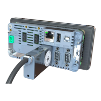
- Setup Switch Sealing: The process begins by positioning the setup switch cover over the setup switch and the two associated closure screws. This cover physically obstructs access to the switch. A destructible sticker is then placed over the center of this cover, extending onto the side of the enclosure. This ensures that the cover cannot be removed without damaging the sticker. The visual representation in Figure 1 clearly illustrates this placement, showing the sticker bridging the cover and the device body.
- Load Cell Connection Sealing (Method 1 - Adaptor Cover): For the load cell connection, one option involves using a load cell connector adaptor cover. This cover is placed over the load cell connector adaptor. Subsequently, a sticker is applied across this cover, securing it in place and indicating any tampering. This method is also depicted in Figure 1, demonstrating how the sticker spans the cover to the device.
- Load Cell Connection Sealing (Method 2 - Direct Connection): An alternative method for sealing the load cell connection, particularly for DB9 load cell connections, involves placing a sticker directly across the load cell connector itself. This is shown in Figure 2. This method is suitable when an adaptor cover is not used or when a more direct sealing approach is preferred. The sticker effectively covers the connection point, making any disconnection or manipulation evident.
- Tamper Evidence: The destructible nature of the stickers is a key feature. If an attempt is made to remove the cover or access the switch/connection, the sticker will tear or break, providing clear evidence of tampering. This is vital for regulatory compliance and audit trails.
-
Maintenance Features:
- Inspection: Regular visual inspection of the stickers is the primary maintenance activity. Any signs of damage, tearing, or removal indicate a potential breach and necessitate further investigation.
- Replacement: If a sticker is found to be damaged or if the device's calibration needs to be re-accessed (e.g., for recalibration or maintenance), the existing sticker must be carefully removed (which will destroy it) and replaced with a new one after the necessary work is completed and the covers are re-secured. This ensures continuous protection of the calibration settings.
- Simplicity: The simplicity of applying and inspecting stickers makes this a low-maintenance solution. No specialized tools are required for routine checks.
Sealing with Wire and Lead Seals
This method offers a more robust and traditional approach to sealing, often preferred in environments where a higher level of security and tamper evidence is required. It involves threading a wire through specific loops and securing it with a lead seal, creating a physical barrier that is difficult to bypass without leaving clear evidence.
-
Function Description: Wire and lead seals provide a physical and highly visible means of securing the setup switch cover and the load cell connection. By threading a wire through designated loops on the covers and the device, and then crimping it with a lead seal, a continuous physical barrier is created. This method not only secures the covers but also indirectly seals access to two of the enclosure closure screws, adding an extra layer of protection. The integrity of the seal is easily verifiable, as any break in the wire or damage to the lead seal indicates tampering.
-
Usage Features:
- Equipment Required: This method requires wire and lead seals, a setup switch cover, and a load cell connection cover. These are standard components for this type of sealing.
- Setup Switch Sealing: The setup switch cover is placed in position, covering the setup switch and the two closure screws. The wire seals are then inserted through the loops provided on the cover and the device. Once the wire is correctly routed, the lead seals are closed (crimped) to secure the wire, as illustrated in Figure 3. This creates a tamper-evident loop that prevents the removal of the cover.
- Load Cell Connection Sealing: Similarly, the load cell connection cover is placed over the load cell connector. A wire seal is then inserted through the connections cover, utilizing the loops provided for this purpose. The lead seals are then closed to secure the wire, mirroring the process for the setup switch cover, and also shown in Figure 3. This ensures that the load cell connection cannot be accessed without breaking the seal.
- Integrated Security: A significant feature of this method is its ability to simultaneously secure the covers and indirectly protect the enclosure closure screws. By routing the wire through points that also encompass the screws, the act of breaking the seal becomes necessary to access the screws, thereby enhancing overall device security.
- Visual Tamper Evidence: The physical nature of the wire and lead seal provides immediate visual evidence of tampering. A broken wire, a deformed lead seal, or any sign of manipulation clearly indicates an attempt to bypass the security measures. Figure 3 provides a detailed view of the wire seal loop locations, making it clear where the wire should be routed for effective sealing.
-
Maintenance Features:
- Inspection: Regular visual inspection of the wire and lead seals is critical. Checks should focus on the integrity of the wire (no cuts, breaks, or signs of rejoining) and the lead seal (no deformation, cracks, or signs of being opened and re-crimped).
- Replacement: If a seal is found to be compromised, or if access to the device's internal components is required for maintenance, recalibration, or repair, the existing wire and lead seals must be cut and removed. After the necessary work is completed and the covers are re-secured, new wire and lead seals must be applied according to the described method. This ensures that the device remains protected after any intervention.
- Durability: Wire and lead seals are generally more robust than stickers and can withstand certain environmental conditions better, offering a durable sealing solution.
In summary, both sealing methods described in the document for the C510, C520, and C527 devices are designed to protect the integrity of calibration settings and prevent unauthorized access. The choice between stickers and wire/lead seals may depend on specific regulatory requirements, environmental conditions, and the desired level of tamper evidence. Both methods emphasize clear visual indicators of tampering, facilitating easy inspection and ensuring compliance with metrological standards. The detailed instructions and accompanying figures provide a comprehensive guide for proper implementation, ensuring that the devices maintain their calibration integrity throughout their operational life.