3
TO ERASE AN ADDRESS FROM RECEIVER
While in WRITE MODE (SW1, position 7 ON), press push-button S2 as often as needed until the desired transmitter location appears on the LEDs. The chosen zone
and transmitter LEDs will blink.
Press and hold tamper switch S1, then press push-button S2 for three seconds. Release push-button and tamper switch. All LEDs blink and buzzer sounds. Then
desired zone blinks and transmitter LED lights steadily. This will indicate removal of transmitter from system's memory.
Set SW1, position 7 to OFF to return to NORMAL MODE.
TROUBLE OUTPUT OPERATION
TROUBLE OUTPUT is activated while 1 or more (up to 4) of SW2 switches are set to ON. TROUBLE signals will activate the TROUBLE relay and together will
illuminate the red event LEDs. TROUBLE outputs are not affected by the ARM/DISARM setting of the system. Table 4 below describes TROUBLE signals and the SW2
TROUBLE output settings.
Table 4: Output DIP - switch SW2 (4 positions) determines which TROUBLE signals produce an output at the TROUBLE terminals. The TROUBLE output contacts are
Normally Closed.
SW2 Position TROUBLE Output when set ON Corresponding LED display on receiver
1 Low Battery. Low battery
2 Tamper – from transmitter (RWX34S, RWT72M, RWT92) or from Nova receiver. Tamper
3 Supervision – Gives an output if no signal is received from supervised transmitter for 3 or 8 hours (time
depends on setting of jumper JP1).
Status
4 Jamming – Gives an output if there is interference or jamming on channel for 30 seconds or more. Low battery + Status
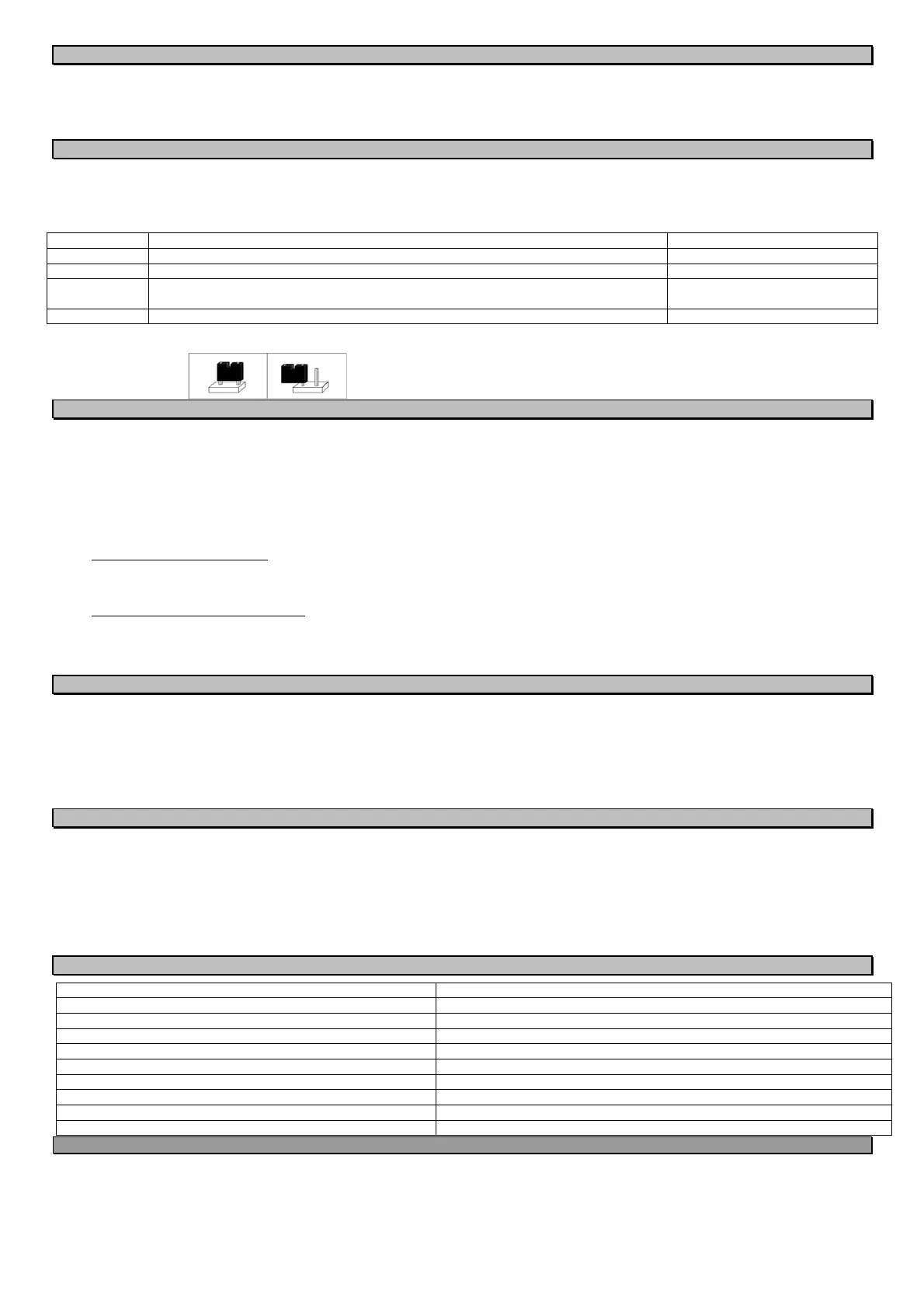
Jumper JP1: Jumper JP1 determines the supervision period. Supervised transmitters (RWX34S, RWT72, RWT92) send signals periodically. Lack of signal for a period
determined by the jumper setting will cause a STATUS alarm on the receiver.
Jumper Placement Supervision Time
On both JP1 pins 8 hours
On one JP1 pin or removed 3 hours
NORMAL MODE
Perform a functional test of the system by causing each transmitter to alarm, and noting proper response from the receiver and control panel.
When your receiver is in NORMAL MODE:
1. SW1 positions 7 & 8 have been set to OFF.
2. You may ARM/DISARM the receiver by use of an appropriate transmitter and/or by arming and disarming the control panel.
3. During ARM periods:
All LEDs will be extinguished
Alarm signals will be received from transmitters and handled appropriately.
No LED display can be seen on the receiver.
4. During DISARM periods:
If you have chosen LATCH display:
Display will appear automatically and will continue until the next ARM.
All events will be shown continuously, zone by zone, on the appropriate LEDs.
Events occurring to transmitters defined as 24 HOURS will activate zone relay and will be added to the LATCH display.
If you have chosen MOMENTARY display:
There will be no automatic LED indications of events that took place during previous ARM period. You may view up to 10 events by entering Event Retrieval
from Memory. Messages sent from transmitters can each be viewed for 2 seconds.
Events occurring to transmitters defined as 24 HOURS will activate zone relays and will appear in MOMENTARY mode.
EVENT RETRIEVAL FROM MEMORY
Up to 10 most recent events may be retrieved and displayed while receiver is disarmed. Note that last event will be displayed first.
1. Press the MEMORY push-button.
All LEDs blink, then the most recent event is displayed by lighting the relevant zone LED, the transmitter LED and an event LED. If the event was tamper or
jamming of the receiver, only the red event LED or LEDs will light.
2. Pressing the MEMORY push-button up to 10 times will display on the LEDs the last 10 events as above.
3. After all events have been displayed, pressing MEMORY push-button once more will return the receiver to NORMAL mode.
You may return to NORMAL mode at any time by pressing push-button MEMORY for 3 seconds. Receiver will return automatically to NORMAL mode if MEMORY
button is not pressed for 1minute. The memory will be cleared after getting into the WRITE MODE.
APPLICATION QUESTIONS & ANSWERS
Can I have supervised transmitters & detect low battery & tamper when I use Basic Installation Setup?
Yes. Connect the TROUBLE output of the receiver to a Trouble zone on your panel. Set the required SW2 positions to ON. Set SW1 position 4 to ON when you send a
WRITE transmission from a detector you want supervised (RWX34S, RWT72M, RWT92). Do not forget to return SW1 position 4 to OFF when sending WRITE from a
non-supervised portable transmitter (RWT50P, RP128T4Z, RWT54).
What is a Restorable Transmitter?
A restorable transmitter sends an alarm signal when an alarm occurs, and another ("restore") signal when the alarm situation ends. The ON/OFF transmitters also
have this characteristic. When NOVA IV receives an alarm signal from one of these devices, it operates the output relay and holds it until it receives a restore signal,
instead of releasing the relay after two seconds. This means that if RWT72M is used to detect an open window, the panel cannot be armed with the window open, just
as when a window switch is wired directly to the panel.
SPECIFICATIONS
Operating Voltage and Current 10 to 15 Vdc, 70 mA. typical, outputs NO
Receiver Type Superheterodyne
Outputs for NOVA IV 4 Alarm relay outputs plus 1 trouble relay output
Maximum number of transmitters for NOVA IV 16 (maximum 4 per zone)
Transmitter Addresses Over 16 million
Frequency Options 868.65 MHz as per European Standards
Output Contacts 0.5 A at 24 Vdc maximum
Dimensions (Width / Height / Depth) W: 145 mm (5.7 in.) / H: 90 mm (3.54 in.) / D: 42 mm (1.65 in.)
Weight 200 gr. (7 oz.)
Temperature Range 0 to 50C (32 to 122F)
CAUTION NOTICE
Operation is subject to the following two conditions:
This device may cause interference.
This device must accept any interference, including interference that may cause undesired operation of the device.
Changes or modifications not expressly approved by RISCO Group may void the user’s authority to operate this equipment.
The communication quality of this unit may be affected by its surrounding environment. Nearby electrical equipment may interfere with its normal operation.
The operation of this unit must, therefore, be tested at each installation since its transmission quality may vary as a result of operational conditions.
Simultaneous transmissions from two different units may cause message interference resulting in loss of information.
 Loading...