Do you have a question about the Risco RK350DT and is the answer not in the manual?
Guides selection of optimal mounting location based on detection range and pet immunity.
Provides step-by-step instructions for physically attaching the detector to its wall bracket.
Details PIR detection range based on mounting height and swivel angle for optimal performance.
Explains how to configure the detector for Standalone or RISCO BUS modes via DIP switches.
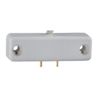
Illustrates the terminal wiring connections required for the detector in standalone mode.
Provides detailed DIP switch configurations for various detector settings in standalone mode.
Details how to assign a unique BUS ID to the detector using DIP switches 1-5 for RISCO BUS integration.
Guides on configuring system settings and adding the detector to the RISCO BUS system.
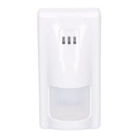
Describes the meaning of various LED indications during walk test and normal operation.
Details the internal self-test mechanism for PIR and MW channels and fault indication.
| Microwave Frequency | 10.525 GHz |
|---|---|
| PIR Element | Quad Element |
| Coverage Angle | 90° |
| Operating Voltage | 9-16VDC |
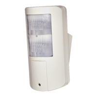
| Mounting | Wall or Corner |
| Tamper Protection | Yes |
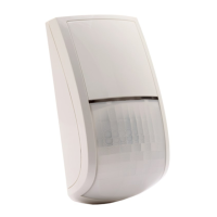
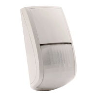
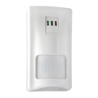
| Type | Dual Technology Detector |
| Technology | Microwave + PIR |
| Pet Immunity | Up to 36 kg |
| Alarm Output | NC |
| Tamper Output | NC |
| Humidity | 95% max |
| Compliance | EN 50131-2-4 |
| Detection Range | 15m (50ft) |