Mounting
2
1
3
Model / Lens Wide angle (H) Corridor (LLPL02) (H) Curtain (LLPL03) (H)
Numéro de Modèle
Lentille grand angle Lentille couloir (LLPL02) Lentille rideau (LLPL03)
Referencia / Modelo
Lente gran angular Lente de corredor (LLPL02) Lente cortina (LLPL03)
Codice prodotto
Lenti grandangolo Lenti corridoio (LLPL02) Lenti a tenda (LLPL03)
Códigos Lente de ângulo aberto Lente de corredor (LLPL02)
Lente de cortina (LLPL03)
Symbol / Model Soczewka szerokokątna Soczewka korytarzowa (LLPL02) Soczewka kurtynowa (LLPL03)
PIR 41502
2m-3m (6’7’’-8’10’’) 2.5m (8'2.4'') 1.5m (Typical)
EN
FR
SP
IT
PR
PL
H
PIR 41502 Curtain
(LLPL03)
1
3
0
2 4 6 8 10 1514120
2
m
5
7
4
6
Top View
Side View
2 4 6 8 10 1514120
m
2
4
6
8
10
0
2
4
6
8
10
6°
PIR 41502 Corridor Lens
(LLPL02)
2 4 6 8 10 1514120
m
2
4
6
8
10
0
2
4
6
8
10
6°
Top View
Side View
1
3
0
2 4 6 8 10 1514120
2
m
5
4
PIR 41502 Wide Angle Lens
2
4
6
8
0
2
4
6
8
2
4 6 8
10 1514120
m
90°
10
10
Top View
Side View
1
3
0
2 4 6 8 10 1514120
2
m
5
4
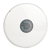
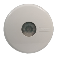
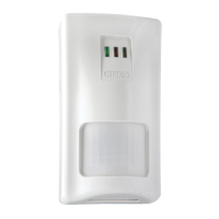
PIR Digital Detector
Model: PIR 4150200A
2
2
2
2
1
1
1
3
1 2 3
EN
FR
SP
IT
PR
PL
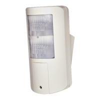
Wall mounting Corner mounting
Montage mural Montage en coin
Montaje en pared Montaje en rincón
Montaggio su parete piana Montaggio ad angolo
Montagem na parede
Montagem no canto
Mocowaniu do ściany
Mocowaniu narożnym
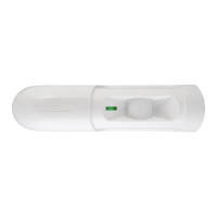
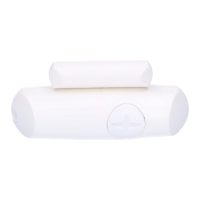
Swivel knockout
Miejsce mocowania uchwytu
Terminal Wiring
IT
Collegamento dei Morsetti
12VDC: Ingresso alimentazione
ALARM: Relè d’allarme NC libero da tensione
TAMPER: Relè di tamper NC libero da tensione
PR
Terminais de Conexão
12VDC: Entrada de alimentação
ALARME: Relé de contato seco NF
TAMPER: Relé de contato seco NF
PL
Podłączenie
12VDC: Zasilanie czujki
ALARM: Zaciski alarmowe NC
TAMPER: Zaciski sabotażowe NC
TAMPER
LED
ALARM
-12V+
Bornes de Conexión
12VDC: Entrada de alimentación
ALARM: Relé de Contacto Seco N.C.
TAMPER: Relé de Contacto Seco N.C.
SP
Connexion
12VDC : alimentation électrique
ALARM : contact sec NF d'alarme
TAMPER : contact sec NF d'autoprotection
FR
EN
Terminal Connection
12VDC: Power supply inputs
ALARM: NC Dry Contact switch
TAMPER: NC Dry Contact switch
LED: 12VDC activated input.
LED is enabled if it is not connected or the
12VDC is applied.
The LED is disabled if GND is applied.
LED: 12VDC activated input.
LED is enabled if it is not connected or the
12VDC is applied.
The LED is disabled if GND is applied.
LED: 12VDC activated input.
LED is enabled if it is not connected or the
12VDC is applied.
The LED is disabled if GND is applied.
LED: 12VDC activated input.
LED is enabled if it is not connected or the
12VDC is applied.
The LED is disabled if GND is applied.
LED: 12VDC activated input.
LED is enabled if it is not connected or the
12VDC is applied.
The LED is disabled if GND is applied.
LED: 12VDC activated input.
LED is enabled if it is not connected or the
12VDC is applied.
The LED is disabled if GND is applied.
EN
SP
Swivel Mounting
1. Remove the swivel entry knockout and cable entry
knockouts located on the detectors base.
2. If required, remove wires entry knockouts on the swivel.
3. Attach the swivel to the selected location on the wall or the
ceiling.
4. Attach base to swivel using the supplied plastic washer and
attaching screw.
5. Feed the cables into the detector base.
PR
FR
Swivel Mounting
1. Remove the swivel entry knockout and cable entry
knockouts located on the detectors base.
2. If required, remove wires entry knockouts on the swivel.
3. Attach the swivel to the selected location on the wall or the
ceiling.
4. Attach base to swivel using the supplied plastic washer and
attaching screw.
5. Feed the cables into the detector base.
IT
PL
Swivel Mounting
1. Remove the swivel entry knockout and cable entry
knockouts located on the detectors base.
2. If required, remove wires entry knockouts on the swivel.
3. Attach the swivel to the selected location on the wall or the
ceiling.
4. Attach base to swivel using the supplied plastic washer and
attaching screw.
5. Feed the cables into the detector base.