Do you have a question about the Risco Lumin8 4012 and is the answer not in the manual?
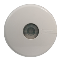
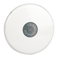
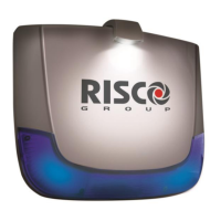
Introduction to the LuMIN8 sounder, its design, spotlight, SLT strobe, and tamper protection.
Detailed guide for mounting, wiring, and initial setup of the sounder unit.
Configuration of dipswitches for SAB/SCB, sounder current, sound type, and BUS/Stand Alone selection.
Explanation of each terminal on the LuMIN8 sounder and their functions.
Methods for connecting and triggering the sounder in Stand Alone mode, including monitored types.
Wiring diagrams for serial (BUS) connections to GT and ProSYS FreeCom control panels.
Diagram for connecting multiple sounders in parallel in Stand Alone mode to GT panels.
Steps for powering up, testing, and initial commissioning of the LuMIN8 sounder.
Lists key technical parameters like power, current, sound level, dimensions, and compliance.
Cross-reference for LuMIN8 terminal connections to various third-party control panels.
Guidelines for maximum cable lengths in serial mode based on cable type and configuration.
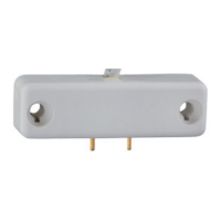
Visual instructions for installing the optional LuMIN8 lamp spotlight accessory.
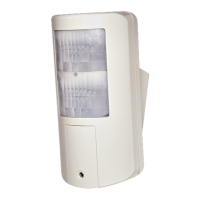
The RISCO Group's LuMIN8 External Sounder is a high-performance and reliable security device designed to provide an exclusive finishing touch to security installations. It can be connected to any alarm system or integrated into RISCO Group's ProSYS FreeCom Integrated Security System or GT series Control Panels via a serial BUS.
The LuMIN8 serves as a professional sounder with a logo illuminator. When installed in BUS serial mode, it supports remote parameter setting and diagnostics, which helps save time and money on installation and maintenance by reducing the need for repeat site visits. The device incorporates a patent-pending spotlight and a long-life SLT strobe for illumination.
| Brand | Risco |
|---|---|
| Model | Lumin8 4012 |
| Category | Security Sensors |
| Language | English |