Used to select SAB or SCB mode for the sounder.
ON (SCB): Current for the sounder will be drawn from the sounder’s rechargeable
battery.
OFF (SAB): Current for the sounder will be drawn from the control panel.
The operation of the dipswitches varies according to the sounder operation mode (BUS or
Stand Alone) as defined by SW5.
Stand Alone Mode (SW5 OFF):
SW2 (A1) Used to control the Sounder Current.
ON: Low current mode. The sound output will be reduced to 105dB 150mA
(1 piezo).
OFF: Normal current mode. The sound output will be 111dB 350mA (1 piezo).
SW3 (A2): Used to select the Sounder Sound.
ON: Low Sweep tone
OFF: High Sweep tone
SW4 (A3): Used to define Engineer Maintenance Mode (2 options available).
ON: The Engineer may disable the box tamper (built-in bell tamper ring) by removing
the 12V+ for 3 seconds. This mode will be indicated by a single flashing LED. To
return the sounder to the normal mode, remove the power for 10 seconds.
OFF: Application of 12V to the SET+ input will place the sounder in Engineer
Maintenance Mode. When in Engineer Mode, the sounder tamper signal is
active.
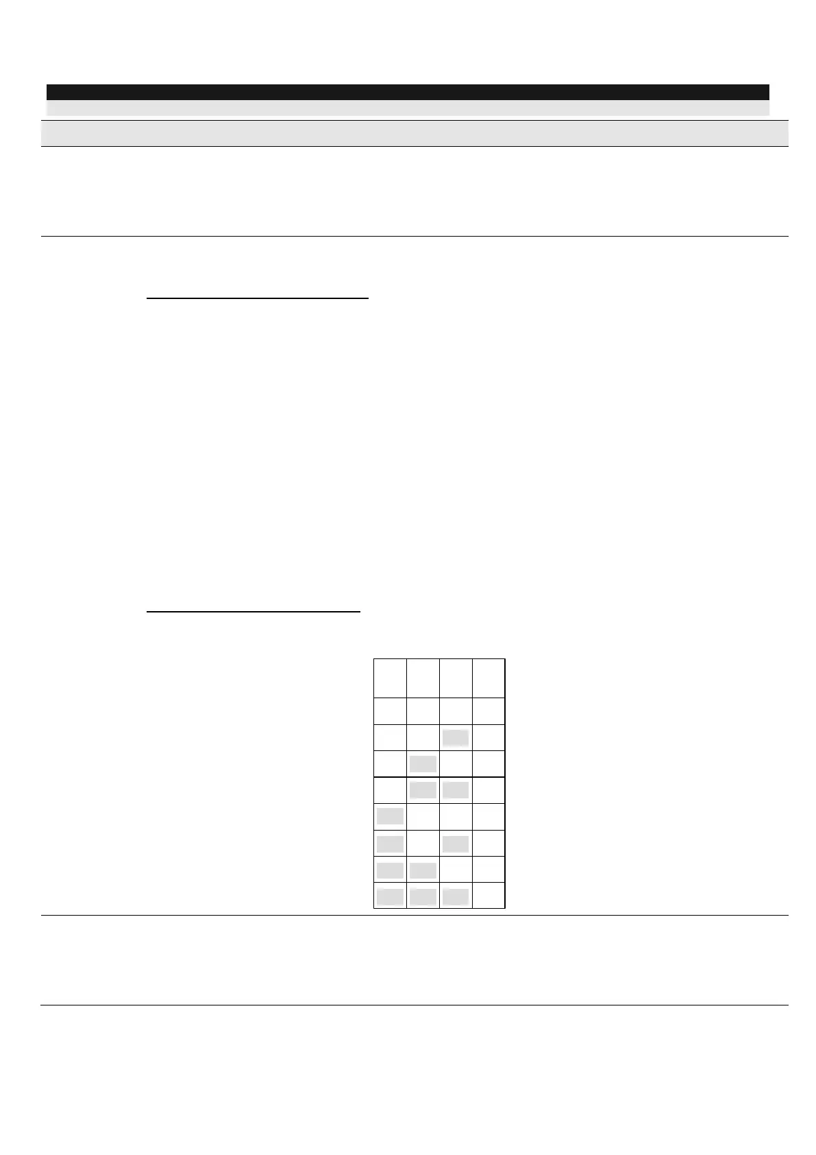
BUS (Serial) Mode (SW5 ON):
SW2-SW4: Used to set a unique ID number for the sounder when connected in serial
mode (ProSYS or GT serial control panels).
Defines the operation mode of the sounder.
ON (BUS): BUS (Serial) mode. Use when connecting to ProSYS Freecom or GT
control panels.
OFF (STD): Stand Alone mode.