EasyManua.ls Logo

Risco Lumin8 Delta 4022 - User Manual

Risco Lumin8 Delta 4022
16 pages
Print Icon
To Next Page IconTo Next Page
Loading...
Installation Instructions
Models: Lumin8 4012
Lumin8 Delta 4022
Question and Answer IconNeed help?

Do you have a question about the Risco Lumin8 Delta 4022 and is the answer not in the manual?

Summary

Installation

Dipswitch Settings

Stand Alone Mode Dipswitch Configuration

Details dipswitch settings for sounder current, sound type, and maintenance mode.

BUS (Serial) Mode Dipswitch Configuration

Explains dipswitch settings for assigning unique IDs in serial mode.

Terminal Block Wiring

Sounder Trigger Connection - Stand Alone Mode

Monitored Trigger

Detects sounder activation and tamper if the trigger wire is disconnected.

Non Monitored Negative Trigger

Uses a switched negative trigger signal directly wired to the TRIG terminal.

Non Monitored Positive Trigger

Uses a switched 12V positive trigger signal directly wired to the TRIG terminal.

Monitored Negative Trigger

Monitors negative trigger signals using a 2K2 resistor or direct connection.

Sounder Trigger Connection - Stand Alone Mode to GT Control Panel, Parallel Mode

Sounder Trigger Connection - Serial Mode, GT Control panels

Sounder Trigger Connection - Serial Mode, ProSYS FreeCom

Sounder Trigger Connection - Serial Mode to GT Control Panel, Parallel Mode

Commissioning

Technical Specification

Overview

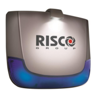
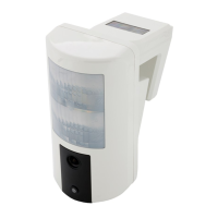
The RISCO Group's LuMIN8 External Sounder is a high-performance and reliable security device designed to provide an exclusive finishing touch to security installations. It can be connected to any alarm system or integrated into RISCO Group's ProSYS FreeCom Integrated Security System or GT series Control Panels via a serial BUS.

Function Description:

The LuMIN8 serves as a professional sounder with a logo illuminator. When installed in BUS serial mode, it supports remote parameter setting and diagnostics, which helps save time and money on installation and maintenance by reducing the need for repeat site visits. The device incorporates a patent-pending spotlight and a long-life SLT strobe for illumination.

Important Technical Specifications:

  • Input DC Power: Regulated 13.0-14.2V
  • Quiescent Current: 23mA (for both Single Piezo and Twin Piezo models)
  • Sounder Current (Regulated):
    • Single Piezo: 350mA
    • Twin Piezo: 450mA
  • Sounder Current (Quiet Mode):
    • Single Piezo: 150mA
    • Twin Piezo: 180mA
  • Strobe Current: 10mA (for both Single Piezo and Twin Piezo models)
  • Battery Charging Current: 15mA
  • Speaker Sound Level:
    • Single Piezo: 111dBA
    • Twin Piezo: 114dBA
  • Strobe Light: Surface Light Technology SMT LED
  • Strobe Lens: Polycarbonate, available in amber, red, or blue
  • Strobe Flash Rate: 60 times per minute (maximum)
  • Back-up Battery (Rechargeable): Ni-MH rechargeable 8.4V, 280mA/h
  • Ingress Protection:
    • IP65 (For encapsulated PCB)
    • IP44 (For other sounder components)
    • IK 08
  • Operating Temperature: -25°C to 60°C (-13°F to 158°F)
  • Humidity: 95% maximum
  • Dimensions (W x L x H):
    • Lumin8: 74mm x 273mm x 230mm
    • Lumin8 Delta: 50mm x 277mm x 236mm
  • Compliance: EN50131-1 Grade 3 Environmental Class IV

Usage Features:

  • Logo Illumination: Features a patent-pending spotlight lamp to illuminate your logo.
  • Strobe: Equipped with a long-life SLT strobe.
  • Housing: Made from UV-treated vandal-proof polycarbonate. An optional internal metal cover provides double skin protection.
  • Power Modes: Selectable SAB (Self-Actuating Bell) or SCB (Self-Contained Bell) modes.
    • SCB Mode: Current for the sounder is drawn from its rechargeable battery.
    • SAB Mode: Current for the sounder is drawn from the control panel.
  • Battery Management: Includes an auto-recharging battery circuit.
  • Tamper Protection: Double tamper protection for both wall and cover.
  • Engineer Mode: Supports remote and local engineer modes for maintenance and configuration.
  • Strobe Activation: Flexible strobe activation when connected in serial mode.
  • Diagnostics and Control: Remote diagnostics and control capabilities when connected in serial mode.
  • Power Protection: Protection from inverted power supply connection.
  • Audible Confirmation: Provides audible confirmation of set/unset actions.
  • Sounder Current Control (Stand Alone Mode):
    • Low Current Mode (ON): Sound output reduced to 105dB with 150mA (1 piezo).
    • Normal Current Mode (OFF): Sound output at 111dB with 350mA (1 piezo).
  • Sounder Sound Selection (Stand Alone Mode):
    • Low Sweep Tone (ON)
    • High Sweep Tone (OFF)
  • Engineer Maintenance Mode (Stand Alone Mode):
    • ON: Engineer can disable the box tamper by removing 12V+ for 3 seconds, indicated by a single flashing LED. To return to normal mode, power must be removed for 10 seconds.
    • OFF: Applying 12V to the SET+ input places the sounder in Engineer Maintenance Mode, with the sounder tamper signal remaining active.
  • BUS (Serial) Mode ID Setting: Dipswitches (SW2-SW4) are used to set a unique ID number (1-8) for the sounder when connected to ProSYS or GT serial control panels.
  • Operation Mode Selection (SW5):
    • ON (BUS): Serial mode for connection to ProSYS Freecom or GT control panels.
    • OFF (STD): Stand Alone mode.
  • Triggering Command Selection (Stand Alone Mode - SW6):
    • ON: Positive trigger.
    • OFF: Negative trigger.
  • BUS Protocol Definition (Serial Mode - SW6):
    • ON (PRO): Connection to ProSYS Freecom.
    • OFF (ACT): Connection to GT (NovaActive) control panels.
  • Monitored/Non-Monitored Trigger (Stand Alone Mode - SW7):
    • ON (MON): An internal 4K7 resistor is connected between the TRIG terminal and the HOLD – (0V) terminal for monitored operation.
    • OFF (NM): Not monitored, no 4K7 resistor connected.
  • Tamper Installation Ease (Stand Alone Mode - SW8):
    • ON (TMF): Connects the TMPF terminal to HOLD – (0V).
    • OFF (EXT): TMPF terminal is open.
  • Setting Confirmation Sound: A positive signal to the SET+ terminal activates the setting confirmation sound.
  • External Lamp Activation: The LAMP terminal is for activating an external lamp when connected between LAMP and Hold – (Stand Alone Mode or GT BUS Mode). In ProSYS BUS (Serial) Mode, the lamp is controlled from ProSYS BUS.

Maintenance Features:

  • Installation: The installation process involves opening the screw cover, terminal block cover, using the back plate as a template for marking, drilling holes, pulling cables, firmly screwing the back plate, configuring dipswitches, making terminal block connections, and connecting the battery.
  • Cable Distance Recommendations: Guidelines for maximum cable distances using 7/0.2 alarm cable in serial mode, with options for 4-core and 6-core cables to overcome distance limitations.
  • Commissioning: Before powering up, ensure all dipswitches are in the correct position. Upon power-up, the sounder will sound for 4 seconds (engineer test) if a trigger (including tamper) is present, then cut off. It can only be re-triggered by clearing the original trigger. This 4-second timer is only available at power-up.
  • Sounder Cut-off Time: 15 minutes, or 5 minutes if the supply voltage is less than 13V when triggered.
  • Strobe Flash Behavior: Flashes at 1.25Hz normally. If the control panel appears to be running on battery, it flashes once every 5 seconds.
  • Health and Safety: Suitable ear protection is essential when installing or testing due to the high volume sound produced.
  • Metal Shroud Installation: Instructions for installing the metal shroud are provided separately with the product.
  • Lamp Spotlight Installation: Detailed steps are provided for installing the LuMIN8 Lamp Spotlight.

Risco Lumin8 Delta 4022 Specifications

General IconGeneral
BrandRisco
ModelLumin8 Delta 4022
CategorySecurity Sensors
LanguageEnglish

Related product manuals