Do you have a question about the RITE-HITE Wheel-Lok GWL-2300 and is the answer not in the manual?
| Model | GWL-2300 |
|---|---|
| Brand | RITE-HITE |
| Color | Yellow |
| Function | Vehicle Restraint |
| Material | Steel |
| Compliance | ANSI MH30.3 |
| Type | Mechanical |
| Activation | Manual |
Information about the Planned Maintenance Program (P.M.P.) and contact details.
Covers general warnings, lockout/tagout procedures, and definitions of safety alert levels.
Owner's duty to train operators, provide manuals, and ensure visibility of warnings.
Proper vehicle parking, contact with bumpers, and brake/chock usage.
Following maintenance schedules, handling damaged equipment, and ensuring parts availability.
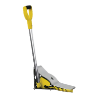
Describes the GWL-2300 as a truck and trailer locking system for dock safety.
Explains the function of internal/external lights and the warning horn.
Introduces major components like Hydraulic Cylinder, Power Unit, Barrier Shaft, Frame Assembly, etc.
Details assemblies and sensors involved in locking and triggering, e.g., Pawl, Trigger, Locking Arm, Sensors.
Describes the initial state with outside green and inside red lights.
Steps and light signals for locking a truck using the LOCK button.
Steps and light signals for unlocking a truck using the UNLOCK button.
Describes the fault mode when the locking mechanism fails, indicated by red lights and alarm.
Procedure for silencing the horn after securing the trailer by other means.
Warning against removing the lock arm with a truck tire present.
Step-by-step guide for manual vehicle release during a power outage.
Warning about hazards and potential damage during snow removal.
Procedure for clearing snow and ice from the unit and approach.
Safety warnings for electrical work and general maintenance requirements.
Covers daily, 90-day maintenance tasks, including cleaning and lubrication.
Covers 180-day and 360-day maintenance tasks, including inspections and operational tests.
Emphasizes immediate replacement of worn or missing dock bumpers.
Safety warnings for electrical hazards and personal injury prevention.
Addresses issues like cylinder extension failure, no lights, and unit faults.
Procedure to test the magnetic reed switch using a multimeter.
Tests for motor winding issues or mechanical binding.
Chart showing LED and output status for various operational states.
Steps to set a new HORN OVERRIDE code.
Procedure to enter diagnostic mode and execute test steps for equipment functionality.
Diagram showing standard electrical connections and component layout.
Diagram illustrating electrical connections for optional modules.
Wiring diagram for the outside light box, showing lamp connections.
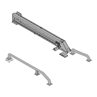
Exploded view of the track assembly components.
Detailed list of part numbers for the track assembly.
Diagram and part list for wheel guides and barrier ramp.
Exploded view and part list for the locking arm assembly.
Diagram and part list for the locking arm trolley assembly.
Exploded view and part list for the pawl assembly.
Diagram and part list for the trigger assembly.
Exploded view and part list for the trigger trolley assembly.
Diagram showing locations of electrical replacement parts.
Detailed list of part numbers for electrical components.
Diagram and part list for signs, decals, and the owner's manual.
Exploded view and part list for the hydraulic power unit.
Diagram of the left-hand track assembly components.
Detailed list of part numbers for the left-hand track assembly.
Diagram and part list for left-hand wheel guides and barrier ramp.
Exploded view and part list for the left-hand locking arm assembly.
Diagram and part list for the left-hand locking arm trolley assembly.
Exploded view and part list for the left-hand pawl assembly.
Diagram and part list for the left-hand trigger assembly.
Exploded view and part list for the left-hand trigger trolley assembly.
Exploded view and part list for the left-hand hydraulic power unit.
Details warranty period, claims, installation, maintenance, and operation requirements.
Outlines limitations on RITE-HITE's liability for loss of use or damages.