EasyManua.ls Logo

RITE-HITE Genisys GWC-1000 User Manual

RITE-HITE Genisys GWC-1000
24 pages
To Next Page IconTo Next Page
Page #1 background imageLoading...
Page #1 background image
NOTICE TO USER . . . . . . . . . . . . . . . . . . . . . . . . . 2
SAFETY . . . . . . . . . . . . . . . . . . . . . . . . . . . . . . . . . 2
FEATURES . . . . . . . . . . . . . . . . . . . . . . . . . . . . . . . 3
INSTALLATION . . . . . . . . . . . . . . . . . . . . . . . . . . . 4
Overview. . . . . . . . . . . . . . . . . . . . . . . . . . . . . . . . . . 4
Change Orientation . . . . . . . . . . . . . . . . . . . . . . . . . 5
ELECTRICAL
Power-Board 110-120V . . . . . . . . . . . . . . . . . . . . . . 8
Power-Board 208-240V (International Only) . . . . . . 9
Restraint Micro Board. . . . . . . . . . . . . . . . . . . . . . . 10
Wiring: Corner-Vu / Leveler-Vu. . . . . . . . . . . . . . . . 12
Wiring: Pedestrian-Vu. . . . . . . . . . . . . . . . . . . . . . . 13
Wiring: Junction Box. . . . . . . . . . . . . . . . . . . . . . . . 15
Wiring: Outside Light Box. . . . . . . . . . . . . . . . . . . . 15
OPERATION
Gen 2 Controls . . . . . . . . . . . . . . . . . . . . . . . . . . . . 16
MAINTENANCE
Planned Maintenance. . . . . . . . . . . . . . . . . . . . . . . 18
TROUBLESHOOTING
LED Status Chart . . . . . . . . . . . . . . . . . . . . . . . . . . 18
PARTS
GWC-1000 . . . . . . . . . . . . . . . . . . . . . . . . . . . . . . . 19
Gen 2 Controls . . . . . . . . . . . . . . . . . . . . . . . . . . . . 20
Outside Light . . . . . . . . . . . . . . . . . . . . . . . . . . . . . 22
Signs. . . . . . . . . . . . . . . . . . . . . . . . . . . . . . . . . . . . 22
WARRANTY . . . . . . . . . . . . . . . . . . . . . . . . . . . . . 24
OVER
2000
ANGLES
-
NONE
2000
+ / - 1 DEG
FINISH
4
0.8
3
2
120
30 120
1.2400
400 1000
1000
0.5
3 6 0.3
6 30
0.230
+ / -UP TO
MILLIMETER TOLERANCES
70.25" (1784mm)
96"
(2438mm)
REF
70" (1780mm)
48
(1220mm)
APPROX
M SVEUM 03/27/2019
FINISH
REFERENCE
SIZE
SCALE
DWG NO
ALL SHEETS ARE THE SAME
PRODUCTS CORPORATION
REV
SHEET
MANUFACTURING ENGINEER
PRODUCTS CORPORATION.
CONFIDENTIAL
®
© 2015 RITE-HIT
REVISION STATUS
DRAWN BY
3
DO NOT SCALE DRAWING
RESPONSIBLE ENGINEER
1 OF 2
INSTR INSTL GWC10
1
MATERIAL
0152682 OMNL wo text
B
SPARKY
A
B
C
D
D
C
B
A
4
3
2
1
4
C
2
1:20
M SVEUM
TITLE
WEIGHT
THIS DOCUMENT IS THE PROPERTY
OF RITE-HIT PRODUCTS
CORPORATION SUBJECT MATTER
HEREIN IS CONFIDENTIAL. DO NOT
USE, REPRODUCE, COPY OR
DISCLOSE EXCEPT WITH WRITTEN
CONSENT OF RITE-HIT
PRODUCTS CORPORATION
REVISION HISTORY
REV DATE DESCRIPTION ECN APPROVED BY
A 2017.8.4 GWC RELEASE ALL DRAWINGS 20170449 M.SVEUM
REF
18"
15"
(381mm)
REF
(2032mm)
REF
REF
80"
48"
REF
(1219mm)
(457mm)
42"
(1067mm)
45" (1143mm)
MINIMUM REF
Model GWC-1000
Publication: AMEN00274 2020-06-26
Genisys™
GWC-1000 Global Wheel Chock
Installation/Service/Owner's Manual
Language: English
Question and Answer IconNeed help?

Do you have a question about the RITE-HITE Genisys GWC-1000 and is the answer not in the manual?

RITE-HITE Genisys GWC-1000 Specifications

General IconGeneral
BrandRITE-HITE
ModelGenisys GWC-1000
CategoryAutomobile Accessories
LanguageEnglish

Summary

SAFETY

Safety Identifications

Describes hazard classifications: DANGER, WARNING, CAUTION, NOTICE.

General Safety Notes

Provides general safety advice, including lockout procedures and electrical precautions.

FEATURES

w/Gen 2 Controls

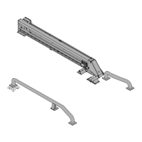
Details components of the GWC-1000 with Gen 2 controls, illustrated with labels.

INSTALLATION

Overview

Presents a diagram with dimensions for the GWC-1000 installation layout.

Change Orientation

Instructions for modifying the GWC-1000 for left-hand use from right-hand use.

ELECTRICAL

Power-Board 110-120V

Wiring diagram for the 110-120V power circuit board.

Power-Board 208-240V (International Only)

Wiring diagram for the 208-240V international power circuit board.

Restraint Micro Board

Wiring diagram for the micro control board, detailing its connections and components.

Wiring: Corner-Vu / Leveler-Vu

Wiring schematic for connecting Corner-Vu and Leveler-Vu sensors to the system.

Wiring: Pedestrian-Vu

Wiring schematic for connecting the Pedestrian-Vu sensor system.

Wiring: Junction Box

Diagram illustrating the wiring connections within the junction box.

Wiring: Outside Light Box

Diagram showing wiring connections for the outside light box.

OPERATION

Gen 2 Controls

Describes the states, default status, and indicator lights for the Gen 2 control system.

Gen 2 Controls Continued

Details additional states (Unlocked) and the Horn Override function for Gen 2 controls.

Horn Override Procedure

Provides steps for using the Horn Override function and returning the system to a stored state.

MAINTENANCE

Planned Maintenance

Outlines a schedule for inspecting and performing maintenance tasks on the wheel chock.

TROUBLESHOOTING

LED Status Chart

A table correlating LED status to system states and fault conditions.

PARTS

GWC-1000 Components

Exploded view and parts list for the main GWC-1000 unit.

Gen 2 Controls Components

Diagram and parts list for the Gen 2 control system enclosure and components.

Outside Light Assembly

Parts list and diagram for the outside light assembly, including bulbs and housing.

Warning Signs

Parts list and diagrams for interior and exterior warning signs.

LIMITED PRODUCT WARRANTY

Warranty Terms and Conditions

Details the limited warranty period, coverage, exclusions, and remedies for the product.

Related product manuals