MAINTENANCE
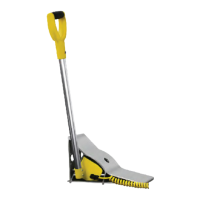
Inspect chock before each use for damage or loose parts.
Replace parts and tighten loose fasteners as needed.
Planned Maintenance
P.M. IN DAYS
INSPECT AND PERFORM:
# 1 180 360
1
Verify horns, inside and outside lights are working.
2
Replace damaged or missing light bulbs and lenses.
3
Repair, remount, or replace outside and inside signs as required.
4 –
Inspect all conduit boxes, control boxes and electrical connections for damage. Repair or replace if worn or damaged.
If control box has evidence of condensation:
a. Inspect conduit. Conduit should be routed to enter through bottom or side of enclosure. A drip leg may be needed if
conduit is filling with water.
b. Inspect seal on cover of enclosure. Seal should be securely adhered to cover with no signs of peeling or bubbling.
Repair or replace if worn or damaged.
c. For non-metallic enclosures, breather vent (part number 122130) may be installed. Vent is NEMA 4X and will not
change environmental rating of control box.
5 –
Perform operational test after all maintenance repairs and adjustments are complete.
6 – –
Check and tighten control box mounting hardware
TROUBLESHOOTING
LED Status Chart
? = Varies (per operation)
A = Alternating
F = O
ITL = Interlock input on
K = Continuous slow chirp
M = Lights when button pressed
P = Pulsing / Flashing
(set to steady using DIP switches)
T = Steady On
MICRO CONTROL BOARD POWER BOARD
INPUTS OUTPUTS
FIELD PUSH BUTTONS 12VDC RELAY 115/230VAC
Dok-Lok Limit Switch 1 [SW1]
Dok-Lok Limit Switch 2 [SW2]
Unlock Interlock [UNLK ITL]
Lock
Unlock
Horn Silence (1/2/3)
Inside Red Light [ISR]
Inside Green Light [ISG]
Corner-Vu Red Light [CVU RD]
Corner-Vu Green Light [CVU GRN]
Leveler-Vu Red Light [LVU RD]
Leveler-Vu Green Light [L-VU GRN]
Outside Red Light [OSR]
Outside Green Light [OSG]
Dok-Lok Horn [HORN]
Restraint Overload LED [YELLOW]
K1 - Green Light Interlock
K2 - Security System Interface
[IF EQUIPPED]
Motor Ouptut #1 [M1/LOCK]
Motor Ouptut #2 (M2/UNLOCK)
12VDC Power Supply OK
TERMINAL BLOCK NO. J13.1 J13.2 J14.3 Membrane J7.16 J7.17 J12.1 J12.2 J12.3 J12.4 J11.2 J11.1 J7.19 N/A J9.3 J10.3 J5.4 J5.3 J2.1-6
POWER BOARD LEDS – – – – – – – – – – – – – – – – – – LD2 LD1 LD7
MICRO CONTROL BOARD LEDS
LD20 LD23 LD30 LD52 LD17 LD19 LD11 LD13 LD18 LD12 LD49 LD48 LD15 LD50 LD9 LD10 LD1 LD3 –
NO.
01.01.00
State/Sequence No.
Locked State T ? ? - - - F P F P F P P F F F T T F F T
01.02.00 Unlocked / Do Not Enter State F ? ? - - - P F P F P F F P F F F T F F T
01.04.00 Fault State ? ? ? - - - P F P F P F P F P F F F F F T
01.04.01 Fault Silenced State ? ? ? - - M A A A P F F F T T F F T
01.07.00 Hooked State T ? ? M M - P F P F P F P F K F F T F F T
01.08.01 Transition State Unlocking F F ITL - - P F P F P F P P F F F T F F T
01.08.03 Locked State Fault F F ? - - P F P F P F P F F F F F F F T
Genisys™ GWC-1000 Global Wheel Chock Installation/Service/Owner's Manual Rite-Hite
®
18 Publication: AMEN00274 2020-06-26

 Loading...