EasyManua.ls Logo

RITS-N IRM203-UNI User Manual

RITS-N IRM203-UNI
2 pages
To Next Page IconTo Next Page
Page #1 background imageLoading...
Page #1 background image
The Radar sensor unit
may be negatively affected
by metal close to or
in the detection area.
( )
Red
Black
White
Green
Yellow
Blue
Gray
Brown
Power (AC/DC 12V~24V)
Safety output
Test Input + (DC 12~24V)
Test Input -
Activation Output
sno
is
nemiD roiretxE .2noitpircseD .1
3. LED Indicators
6. Mounting & Wiring Information
Unit : mm
Max 50mmMax 50mm
DO NOT use any
flat head screws.
WARNING
Accessories
Mounting
template
User Manual
Cable 2.5m
Mounting screws
Cable Length(Min) 80mm
265
60
42.5
Drill screw (mounting) (Ø3.5mm)
③ Use a flathead screwdriver to remove cover.
and power cable (wiring) (Ø10mm)
holes.
① Attach the mounting template so that it is
placed within a 50mm distance from the
bottom edge of the door engine cover.
④ Controller wiring ⑤ Attach the sensor to the door
⑦ Attach the cover.
⑥ Connect the power connector.
1. Insert a flathead screwdriver as shown
2. Turn the screwdriver counterclockwise gently to prise the co
ver from the sensor body
How to remove the cover after installation
Green
LED Indicators
Blue
Red
Standby
Radar detection
IR or IR+Radar detection
w
o
l
o
ot
si y
tiv
i
t
c
elf
er d
e
rar
fnI
d
e
R
+
n
ee
r
G
IRM203-UNI
User Manual
IRM203-UNI
Mounting height of
3m (9.8 ft) or
lower.
Make sure that the
sensor is not directly
exposed to heavy
rainfall.
If possible, ensure there is
no accumulation of snow
or water on the floor.
Ensure the minimum
of reflected sunlight
from the floor.
Use different frequency
settings for sensors
in close proximity.
Mount within 50mm of
the bottom of the door
engine cover.
Ensure that there are
no moving objects in
the detection area.
Ensure that no
condensation gets
onto the sensor.
Infrared detection area setting to maximise pedestrian safety.
Side view
Plan view
Moving door leaf Moving door leaf
Cover
Connector
Indicator LED
(Green/Red/Blue)
Settings display
IR detection area
adjustment
IR sensor
unit
IR angle adjustment screw
Menu button
Change settings button
Set (Apply) button
Menu display
Radar sensor unit
IR sensitivity
volume
IR angle scale
Radar
sensitivity
volume
A
B
A
B
3m
(9.8
ft
)
Max 50mm
1
2
4. Mounting Precautions
AC12V: 300[mA] (Max) / AC24V: 200[mA] (Max)
(
~
),
DC12V: 160[mA] (Max) / DC24V: 80[mA] (Max)
±10 [%] @ 50/60[Hz]
6[mA] @ 24[VDC]
Test input
250[g]
Black
Weight
Power consumption
Color
-20 ~ 50[
°C]
0.5 seconds
AC DC
12~24V
Infrared & Radar sensor detection
Radar detection area adjustment
(Installed height: 2.2 m)
S3 :
3 Step(15°)
S6 :
6 Step(30°)
S9
:
9 Step(45°)
S3
: 3 Step(15°)
S6 : 6 Step(30°)
S9
:
9 Step(45°)
detection module
vertical angle
detection module
vertical angle
Removing/assembling the Radar Sensor Detection Module
1.
Twist with your index finger
in the indicated direction.
2.
Hold and pull forward the upper part of the
module with your index finger.
3.
After removing the module, turn 90 degrees
clockwise, and re-assemble.
90°
8. Detection
※Ensure that detection setting does not exceed the door.
Screw
Near Far
(Default Sensitivity)
Narrow
Wide
Wide
m
m
m
m
1.0 0
.
2
]
m[
0
.
2
1.0
1.0
2.0
2.2
3.0
0
Narrow
IR detection area width adjustment
IR detection area depth adjustment
2 sec
i
Bi
n
U
30 sec
60 sec
CN
ON
CN
ON
without TEST With TEST without TEST
+
+
+
+
Infrared presence
timer setting
Frequency
Setting
Safety Relay
Output
Radar unit
direction
detection
Activation
Relay Output
Factory
reset
Activation
Relay
Output
Configuration
TEST Input
Low reflection
setting
1.0[m] -0.5
0
1.0
2.0
2.2
3.0
3
row
2
row
1
row
[ Far ]
+4
Angle setting
Door
[ Near ]
1.0[m] -0.5
0
row row
1.0[m] -0.5
0
1.0
2.0
2.2
3.0
-8 Angle setting
Door
Question and Answer IconNeed help?

Do you have a question about the RITS-N IRM203-UNI and is the answer not in the manual?

RITS-N IRM203-UNI Specifications

General IconGeneral
BrandRITS-N
ModelIRM203-UNI
CategoryAccessories
LanguageEnglish

Summary

Product Description and Components

Accessories Included

Lists included accessories like mounting template, cable, and screws for installation.

LED Indicators Explained

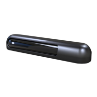
Explains the status indicated by Green, Blue, and Red LEDs on the sensor.

Settings Display

Shows the display used for configuration and adjustments of sensor settings.

Exterior Dimensions Diagram

Mounting and Wiring Information

Controller Wiring Guide

Details the wiring connections for power, activation, safety, and test input signals.

Initialize Sensor Settings

Explains the process to initialize or reset the sensor's configuration to default.

Sensor Settings Configuration

Infrared Presence Timer Setting

Sets the retention time for IR sensor detection, complying with EN16005 standards.

Snow Mode Setting

Disables snow detection to minimize malfunctions during snowy conditions.

Frequency Setting for Interference

Sets different luminescent frequencies to avoid interference between multiple sensors.

Radar Sensitivity Volume Adjustment

Adjusts the sensitivity volume for the radar detection function.

Safety Relay Output Configuration

Sets the contact output status for the safety sensor to NO or NC.

Radar Unit Direction Detection

Sets the radar sensor detection direction to bidirectional or unidirectional.

Activation Relay Output Settings

Sets the output contact status during detection to normally open (NO) or normally closed (NC).

Activation Relay Output Configuration

Sets the status of the relay output when an object or human body is detected.

IR/Radar Activation Settings

Controls the activation of IR and radar sensors for proximity detection.

Test Input Response

Sets the response to test input signals from automatic door controllers per EN16005.

Low Reflection Setting

Manages response to low infrared signal detection, with an option to disable error state.

Factory Reset

Resets all sensor settings to their original factory default values.

Detection Area Adjustment

IR Detection Area Depth Adjustment

Adjusts the depth of the IR sensor's detection area for optimal coverage.

IR Detection Area Width Adjustment

Fine-tunes the width of the IR sensor's detection zone.

Radar Detection Area Adjustment

Adjusts the vertical angle for radar detection area coverage.

Operation Check and Safety Output Timing

Operation Check

Guidance on verifying sensor operation and adjusting detection areas.

Timing of Safety Output Signal

Checks safety output signal timing for automatic door controllers under EN16005.

Troubleshooting Common Issues

Door Fails to Open

Addresses scenarios where the door fails to open despite a person being present.

Erratic Door Operation (Ghosting)

Solves the problem of the door opening and closing erratically without apparent cause.

Automatic Door Stays Open

Troubleshoots issues where the automatic door remains open unexpectedly.

Rain Cover and Spot Finder

Rain Cover Recommendation

Suggests using a rain cover for outdoor installation to protect against snow and rain.

Spot Finder Usage

Explains using a spot finder to accurately locate the IR detection area during commissioning.

Disclaimer and Manufacturer Responsibility