EN
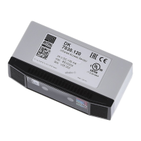
8 Rittal CMC III Infrared Access Sensor
4Assembly
4.1 Assembly instructions
The assembly of the access sensor is made as shown in fig. 2, fig. 3, fig. 4 or fig. 5.
Mount the access sensor so that the front with the transmitter and receiver is pointing to the moni-
tored door.
Stick the enclosed reflective foil on the door and the side wall exactly opposite of the IR sensor.
5 Installation and operation
5.1 Operating and display elements
The operating and display elements are shown in fig. 6.
Key for fig. 6
1 Infrared receiver
2 Infrared diode (transmitter)
3 Multi-LED for the status display
4 CAN bus connection, 24 V
5 CAN bus connection, 24 V
5.2 Installation
Connect the access sensor with a CAN bus connection cable to the CMC III PU or to the neighbour-
ing elements on the CAN bus (fig. 6, item 4, 5).
Display of the status change:
– The two green and the two red CAN bus LEDs on the CAN bus connection flash.
– The multi-LED of the Processing Unit flashes continually in the green – orange – red sequence.
– The multi-LED of the access sensor flashes blue continuously.
Press the "C" key on the CMC III PU (a first audio signal is issued) and keep it pressed for approx.
3 seconds until a second audio signal is issued.
Display of the status change on the CAN bus LEDs:
– Green LEDs light continuously: CAN bus status "OK".
– Red LEDs light continuously: CAN bus status faulty.
Display of the status change on the multi-LED of the Processing Unit:
– Continuous green light: All units attached to the CAN bus have the "OK" status.
– Continuous orange light: At least one unit attached to the CAN bus has the "warning" status.
– Continuous red light: At least one unit attached to the CAN bus has the "alarm" status.
Display of the status change on the multi-LED of the access sensor:
– Continuous blue flashing: Communication over the CAN bus.
– Green flashing: When the measured value changes or, at the latest, every 5 seconds.
– Continuous red flashing: The access sensor has the "open" status.
– Continuous red light: Invalid measured value.
If the installation is not successful: see section 1.1.
Note:
The distance between the IR sensor in the access sensor and the reflective foil must not
exceed 10 cm. Please reposition the access sensor accordingly, if necessary.
Note:
Connection cables in various lengths can be obtained from Rittal.
Assembly, Installation and operation

 Loading...