RS Pag. 11 REV. 08 04/10
UK
flanged).
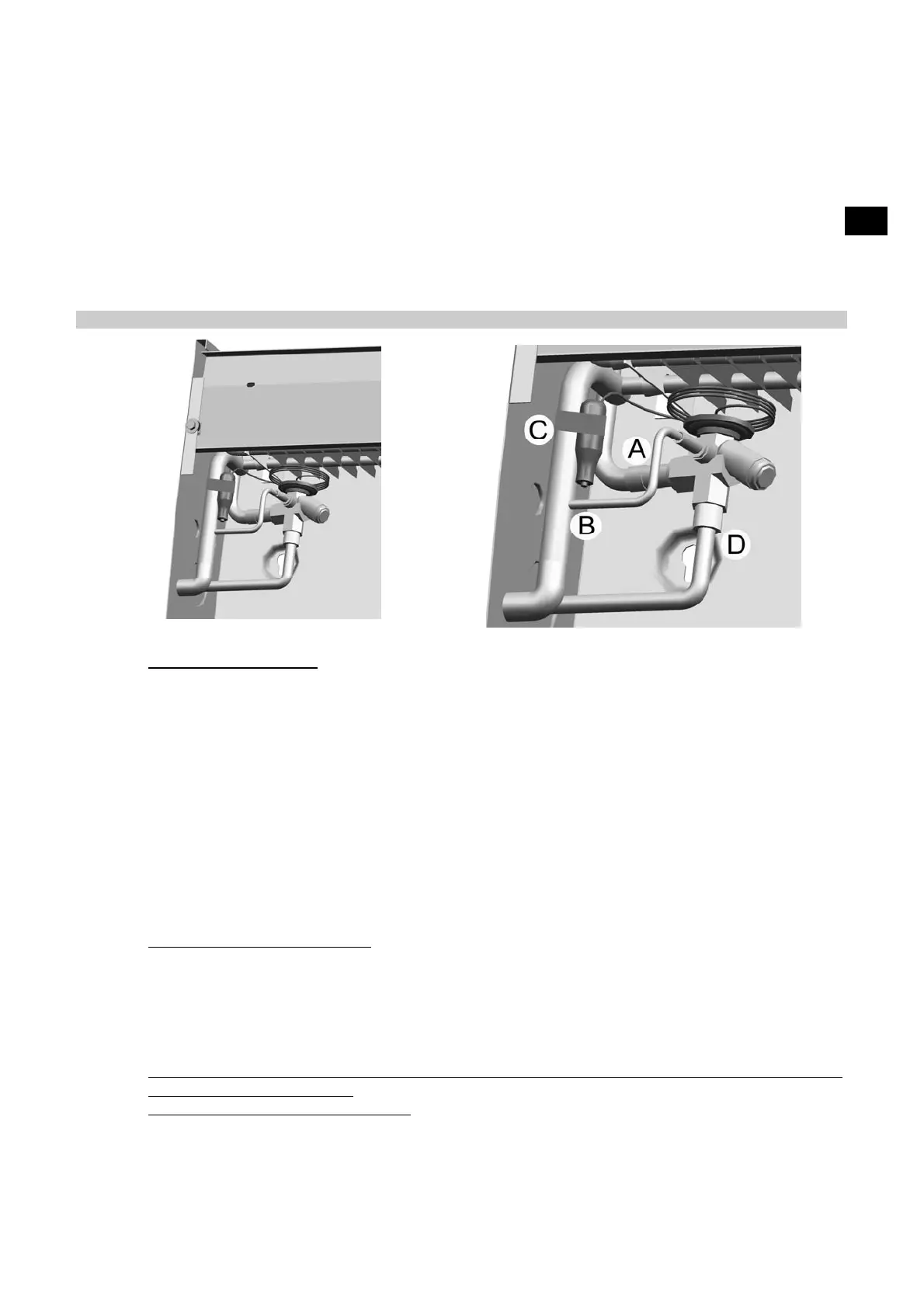
Open the machine, as illustrated in Drawing 3, loosening the screws A and unscrewing the fastening
screws B. Connect the thermostatic valve outlet to the evaporator inlet pipe (Drawing 2, point A).
For models RS3180-RS3180B-RS3290-RS3290B-RS4380-RS4380B only: fit the external equaliser
pipe, which must be welded to the thermostatic valve and to the evaporator manifold, in the position
shown in Drawing 2, point B. Place the thermostatic valve bulb on the suction pipe, just before the
external equaliser pipe, if fitted (Drawing 2 point. C). Fix the bulb on the suction pipe by means of
metal clamps.
Solder on the inlet side of the thermostatic valve, a pipe , previously bent in the proper way, (see
Drawing 2 ; Part D). The pipe will come out from the cooler through the preset hole and will be
connected then to the liquid pipe of the refrigerating system.
Drawing 2
4. 2
Positioning on the ceiling
Once the thermostatic valve is connected, fix the unit cooler to the cold room ceiling.
The unit has to be installed in horizontal position, only by means of the proper fixing slots. The fixing
distances between centers and the position of the fans relating to the cold room walls is shown in
Drawing 1. Keep around the unit enough space for a good air cycling and for a maintenance
operation in safe conditions. The minimum recommended distance from the wall for the motor side is
120 mm (Drawing 1). To assemble, open the machine, as illustrated in Drawing 3, loosening the
screws A and unscrewing the fastening screws B. Fix the machine, using the 4 special slots in the
casing. To fit the defrosting heater, place it in the relevant notches above the coil and fix it into place
using the two springs (G) (supplied).
Proceed to make the refrigerating and electrical connections, as described in the following
paragraphs.
Reposition the conveyor and tighten the screws B and A, as shown in Drawing 3.
Connect the condensation discharge pipe to the pipe union F (supplied).
5.
REFRIGERATING CONNECTION
Connect the evaporator outlet to the refrigerating system suction-pipe (we recommend fitting a
siphon).
Connect the pipe that was previously soldered to the inlet side of the thermostatic valve to the liquid
piping of the refrigerating system.
In order to guarantee a good hermetic seal and reduce break risks, execute all the joints by means of
a “ bell type” welding . If the pipe diameter do not allow that , use proper soldering joints .
During the pipe connection procedure pay attention not to force or modify the position of the header
as this may a cause of breaks.
6.
CONDENSATE DRAIN CONNECTION
The piping for the condensate water drain is to be connected to the 1/2” Gas male connection placed
at the centre of the drip tray (the minimum gradient must be over 20%) . Provide on the cold room
wall, next to the unit cooler, for a hole through which the pipe will come out leading to a siphon trap.
Seal the hole by means of silicon (the features of which will be suitable to the cold room use) in order
to avoid infiltration of warm air. In case of a low temperature cold room the draining line must to be
 Loading...