EasyManua.ls Logo

RMILEC 4047NB20 User Manual

RMILEC 4047NB20
33 pages
To Next Page IconTo Next Page
Page #1 background imageLoading...
Page #1 background image
Introduction of the New Model
NB20 system adopts the latest RF technology, providing very high adjacent
channel rejection ratio and anti-blocking performance, which gives rise to the
outstanding anti-jamming capability of the new system. NB20 receiver can detect the
frequency and amplitude of EMI interference with unbeatable accuracy and precision
based on the extremely low self-noise of -125dBm. The RF performance of NB20
system surpasses the older 4047 systems several orders of magnitude. Furthermore,
NB20 system takes high-speed processor for signal acquisition and output with very
high precision. Its high efficiency transceiver can make full use of band width
limitation and spend shorter time to work out data exchanging,and frequency
calibration. As for operation, NB20 system is compatible with any receiver to
construct a signal relay system. It is highly compatible with mature products on the
present market, such as FUT, JR, HITEC, TDF, FS, XINYI etc. There is no need for
consumers to change the old remote control system or any parameter settings to
directly extend the remote control range. PWM output-and-input is one-to-one. It can
relay signal with very high precision. By using the powerful forwarding of 20
channels, UAVs parameter can be adjusted in the air, and the aerial cameraman and
pilot could work together with single radio. In addition, one transmitter can be shared
by several operators. As for the receiver, either EMI or RSSI signal can be displayed
on LED, which allows debugging according to the visual signal strength. The new
system is of longer remote control distance and higher reliability, because the source
of interference can be more quickly and accurately ruled out.
Question and Answer IconNeed help?

Do you have a question about the RMILEC 4047NB20 and is the answer not in the manual?

RMILEC 4047NB20 Specifications

General IconGeneral
BrandRMILEC
Model4047NB20
CategoryMicrophone system
LanguageEnglish

Summary

Introduction of the New Model

Model Comparison

Similarities

TX/RX operating frequency and frequency hopping details between models.

Differences

Key technical specifications comparison of new and old models.

Transmitter Operation and Features

RF Output Interface

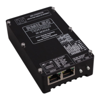
Details on the SMA socket for RF output and antenna connection.

Power and Data Sockets

Description of RJ45 sockets for data and power input on the transmitter.

DIP Switch Configuration

Configuration options via DIP switches SW1 through SW6 for transmitter functions.

Transmitter Buttons

Functions of PB1 (Binding/Failsafe) and PB2 (Data Copy) buttons.

Indicators and Warning Tones

Explanation of RJ45 LEDs, common indicators, and warning tones for status monitoring.

Signal Acquisition System

Power and Data Terminals

Details of 12V DC power input and 20CH PWM signal input terminals.

Pin Definitions and Signal Handling

Pin assignments and rules for PWM, PPM, SBUS, and logic signals.

Receiver Functions and Indicators

Receiver Pin Definitions

Defines pin functions for PWM, PPM, SBUS, and RSSI outputs on the receiver.

Receiver Buttons

Functions of BIND and SCAN buttons for receiver binding and interference scanning.

Receiver Common Indicators

Explanation of RF RX, DONE, ANT1, ANT2 indicator lights for receiver status.

Signal Strength Indicator

How LED lights indicate RSSI and EMI signal strength levels for the receiver.

Installation and Connection Guide

Transmitter Installation

Steps for installing the transmitter, including RF part.

Control Process Example

Example of signal flow from Futaba T12FG to servos via system components.

RF Part Installation

Guidance on connecting the antenna to the transmitter's RF interface.

Data Interface and Power Supply

Connecting RJ45 data interface and powering the signal acquisition system.

Connecting the Be-relayed Receiver

How to connect the be-relayed receiver to the signal acquisition system.

Receiver Installation

Servo, Antenna, and Filter Connections

How to connect servos, antennas, and filter capacitors to the receiver.

Recommended Installation Layout

Guidance on optimal placement of the receiver within the cabin for best performance.

Binding and Data Copy Procedures

Binding Procedure

Step-by-step guide for binding the receiver and transmitter for initial setup.

Receiver Data Copy Function

How to copy frequency hopping data to a second receiver for multi-receiver setups.

Failsafe and Debugging

Failsafe Settings

Configuration and function of failsafe settings for loss of signal.

Debugging Procedures

Steps for testing and debugging system performance and signal strength.

Quick User Guide