Do you have a question about the RNA ESG 1000 and is the answer not in the manual?
Detailed explanation of the control unit's function, load capacity, and pluggable installation.
Lists compliance with Low voltage and EMC directives, and applied harmonized standards.
Specifies mains connection, output voltage, load current, safety fuse, operating modes, and dimensions.
Highlights important symbols, electric danger, and general precautions for safe operation and equipment integrity.
Explains the two operating modes: asymmetrical half-wave and symmetrical full-wave operation.
Details selecting operating mode via load plug and cable fitting colors for 50/60 Hz or 100/120 Hz.
Covers factory adjustments and re-adjustment procedures for minimum/maximum output voltage.
Describes switching the control unit between 230V and 115V mains voltage using an internal switch.
Explains enabling start-stop operation using external contacts or 24V DC voltage signals.
Details how to adjust the soft start run-up time using an internal trimmer for drive protection.
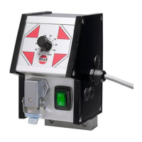
Shows the position of potentiometers, switches, and connectors on the ESG 1000 unit with tokens.
Explains starting the drive using a 10-30V DC signal via an optocoupler for potential-free input.
| Brand | RNA |
|---|---|
| Model | ESG 1000 |
| Category | Control Unit |
| Language | English |