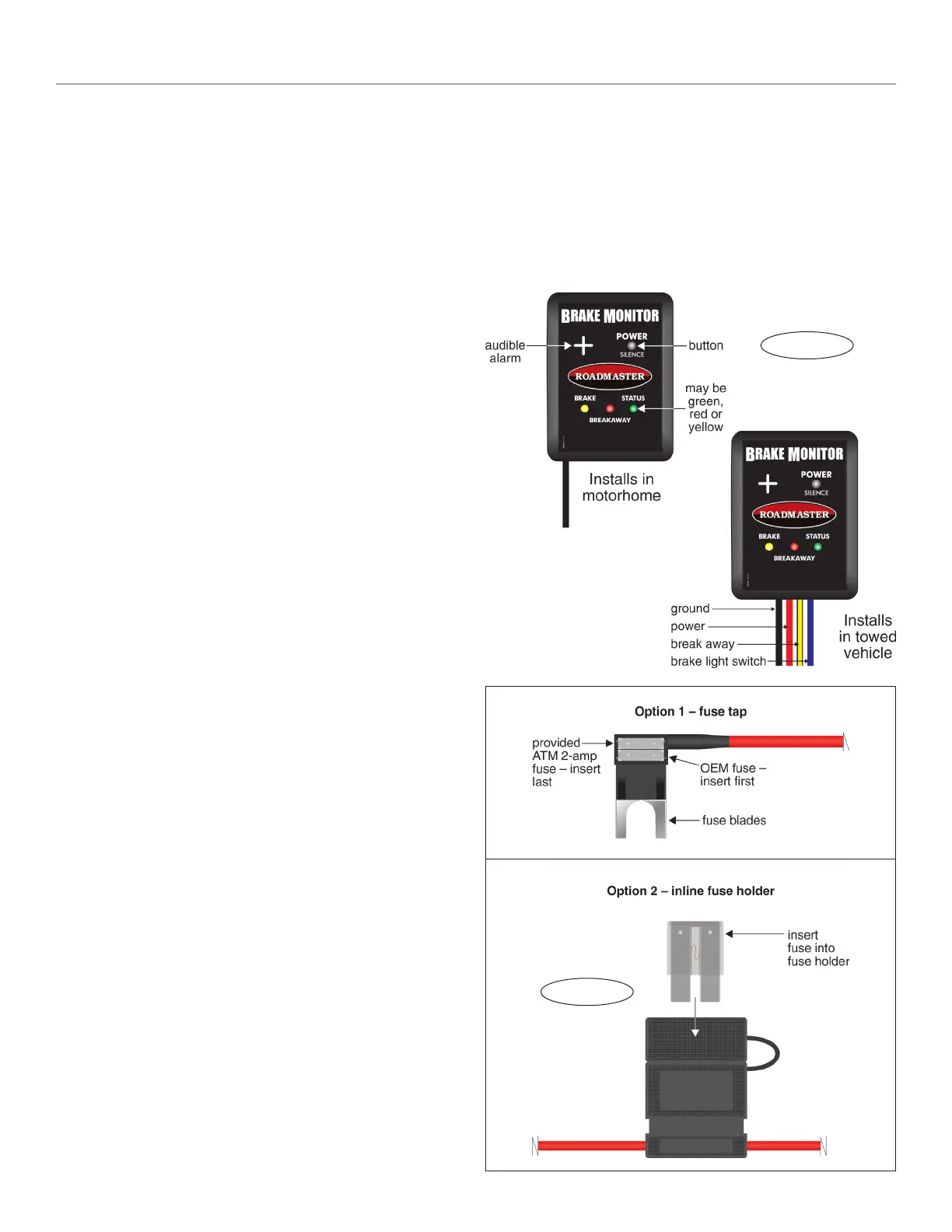
Figure B
Installation and operation
Note: some vehicles will require a supplemental brake
light switch (sold separately). If your vehicle’s brake light
switch doesn’t output a 12-volt signal when the car is in
‘tow’ mode, you must purchase and install a supplemental
brake light switch kit. To learn more visit www.roadmas-
terinc.com or call 800-669-9690.
Installation
Note: if the supplemental braking system to be moni-
tored is a Roadmaster InvisiBrake
®
, check the serial num-
ber before proceeding with the installation. If it’s less than
21603, you must install an optional adaptor, part number
8700-9530.
Note: the most noticeable difference between the mo-
torhome monitor and the towed vehicle transmitter (Figure
A) is the wires extending from them. The transmitter has
four colored wires; the monitor has one black wire.
1. Choose a suitable installation point for the towed ve-
hicle transmitter under the dashboard. This point should be
out of sight but accessible to the installer for troubleshoot-
ing. Any mounting point that doesn’t present an obstacle
to the driver, or interfere with the operation of the vehicle,
is suitable.
2. Attach the wires. If necessary, use a butt connector and
additional 18-gauge wire (not included) to extend the wiring.
• Attach the black wire to any good chassis ground.
• Connect to power: first, determine if you will use the
provided fuse tap or inline fuse holder (Options 1 and 2,
Figure B).
Next, attach either the fuse tap or the fuse holder to
the red wire extending from the transmitter.
Then attach the red wire to any constant 12V
+
source.
CAUTION
The fuse in the fuse tap or fuse holder must be
within six inches of the electrical connection. Other-
wise, a short circuit may cause significant damage to
the towed vehicle’s electrical system, an electrical fire
or other consequential, non-warranty damage.
Note: determine if the vehicle has a ‘retained acces-
sory power’ mode. If so, choose a different circuit to con-
nect the red wire. Otherwise, power to the transmitter will
be lost within a few minutes after the ignition switch is
turned off.
• Attach the yellow wire to the wire on the break away
switch which will be energized during a break away.
• Attach the blue wire to the cold (‘switched’) side of
the brake light switch.
3. Insert the provided fuse into either the fuse tap or fuse
holder (Figure B).
4. Use the included zip ties to attach the transmitter and
professionally secure the wiring.
5. Plug the motorhome monitor into any 12V
+
source in
the motorhome, and attach it with the Velcro strips at any
location where it can be seen by the driver.
Operating the monitor
1. Check the “Status” light:
• If the light is solid green you’re ready to tow.
• If the light is alternately flashing red and green, it’s
not receiving a signal. Pump the towed vehicle’s brake
pedal — the light should now be solid green.
2. To turn the monitor off, press the “Power” button. (The
monitor will always turn off after a few minutes when the
motorhome’s engine is turned off.)
continued on next page
Figure A
 Loading...