EasyManua.ls Logo

Roadstar TRA-2350 Service Manual

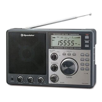
Roadstar TRA-2350
5 pages
To Next Page IconTo Next Page
Page #1 background imageLoading...
Page #1 background image
Service Manual - TRA-2350
R
TRA-2350
Question and Answer IconNeed help?

Do you have a question about the Roadstar TRA-2350 and is the answer not in the manual?

Roadstar TRA-2350 Specifications

General IconGeneral
BrandRoadstar
ModelTRA-2350
CategoryRadio
LanguageEnglish

Summary

TRA-2350 Service Manual

Main Circuit Schematic

Central Control and Display Interface

Details the main IC (U1), its connections, and the LCD display interface.

Input Controls and Power Circuitry

Covers switches, buttons, tuning mechanisms, and power supply connections.

PCB Layout Diagram

Component Placement - Top Layer

Illustrates component placement and routing on the top side of the printed circuit board.

PCB Layout Diagram (Continued)

Component Placement - Bottom Layer

Illustrates component placement and routing on the bottom side of the printed circuit board.

Detailed Schematics

Tuner, RF, and Audio Stages

Diagrams for the radio tuner, RF amplification, and audio output circuitry.
Related product manuals