Bauanleitung, Assembly instructions, Notice de montage
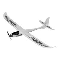
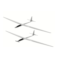
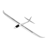
Arcus
19
Bild 29
- Motor mit Luftschrauben-Mitnehmer versehen.
Bild 30
- Motor in den Motorträger einsetzen und mit 2
Senkschrauben befestigen.
Bild 31
- Regler am Empfänger anschließen.
Bild 32
- Motor von hinten in den Rumpfkopf schieben;
Motorträger mit Sekundenkleber verkleben.
Fig. 29
- Fit the propeller driver on the motor output shaft.
Fig. 30
- Place the motor in the motor mount and secure it with
two countersunk screws.
Fig. 31
- Connect the speed controller to the receiver.
Fig. 32
- Fit the motor in the nose of the fuselage from the rear;
glue the motor mount in place using cyano.
Fig. 29
- Munir le moteur de l’entraîneur d’hélice.
Fig. 30
- Installer le moteur dans le support-moteur et fixer avec
deux vis à tête fraisée.
Fig. 31
- Raccorder le variateur au récepteur.
Fig. 32
- Glisser le moteur par l’arrière dans le nez du fuselage et
coller le support-moteur avec de la colle cyanoacrylate.
No.
3117